SX70 camera 125ASA to 600ASA conversion
The scope of this text is to help you do a conversion similar to the one I have done. If you are successful you end up with a switch that lets you choose which kind of film (SX-70 or 600) you want to use.
WARNING: It goes without saying, but nevertheless here it goes: You can seriously damage your camera in the process of doing this modification. It is not for the faint of heart. You have to have some basic dexterity and experience taking apart things. You may need some special tools and you need to have some soldering skills. YOU DO THIS AT YOUR OWN RISK. If you are not sure, just don’t do it, there are people that do something similar for a reasonable amount of money (I will list the ones that I know of at the end, if you do this commercially and want to be on that list just let me know).
As a general rule I will refer to the parts of the camera using the names as in the original Repair Manual that is on the internet. That makes it easier to identify the parts I am referring to. Polaroid is trademark of the Polaroid Corporation.
Step 1: the tools and materials
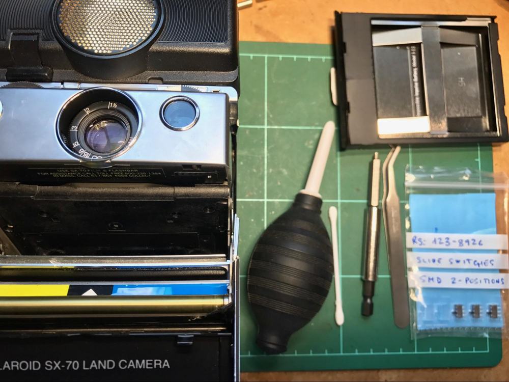
You are going to need some “basic” tools: pliers, soldering iron with a fine tip, a prying tool, a rubber band, toothpicks, cotton swabs and a dust blower (never use canned air) I also use a vise.
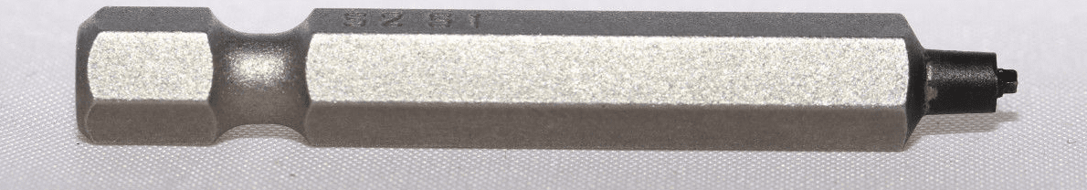
Aside from the usual tools you are going to need what is called a “Polaroid screwdriver” or “SX-70 screwdriver”, since most of the cameras I have come across use a special “square 1mm x 1mm” screws. I do not recommend using a normal or phillips screwdriver since you are most certainly damage your screws, they are rather tight at least the first time you unscrew them.
I have found three options:
- To buy the smallest kind of Robertson square screwdriver (or for that matter any kind of screwdriver) and file it down to the size you need. This is by far the cheapest option.
- This listing on Ebay from Hong Kong (search for “1mm x 1mm Square
Screwdriver for Repair Polaroid SX-70”) This option is quite
expensive but it very nice and very high
quality.

- Finally this Ebay listing from Canada (search for: “1mm x 1mm Polaroid SX-70 Repair Tool Square Head Robertson - From Canada”). This option is by far the cheapest of the “proper” tools and the one that I recommend the most. I have taken apart quite a few SX-70s with it.
Of course you are also going to need some sort of drill tool and a 4mm drill bit. I used one for wood on an electric screwdriver. You can probably do it by hand if you are patient.
As for the “materials” for this project you are going to need some ceramic capacitors, those depend on your SX-70. I have seen conversions on the internet and the value (of the original capacitors) tends to be in the range 680pF to 1024pF. For some reason the Sonar SX-70s I have checked have a value around 1000pF and have an odd shape (at first though they were another resistor). Some people also check/replace the resistor but I don’t usually do that. When I shoot at 600 with flash (MiNT) I usually do it at half power and works great. As for the capacitor to use in the “600” setting I usually go to the low side since SX-70 tends to easily overexpose, in this case around 150pF.
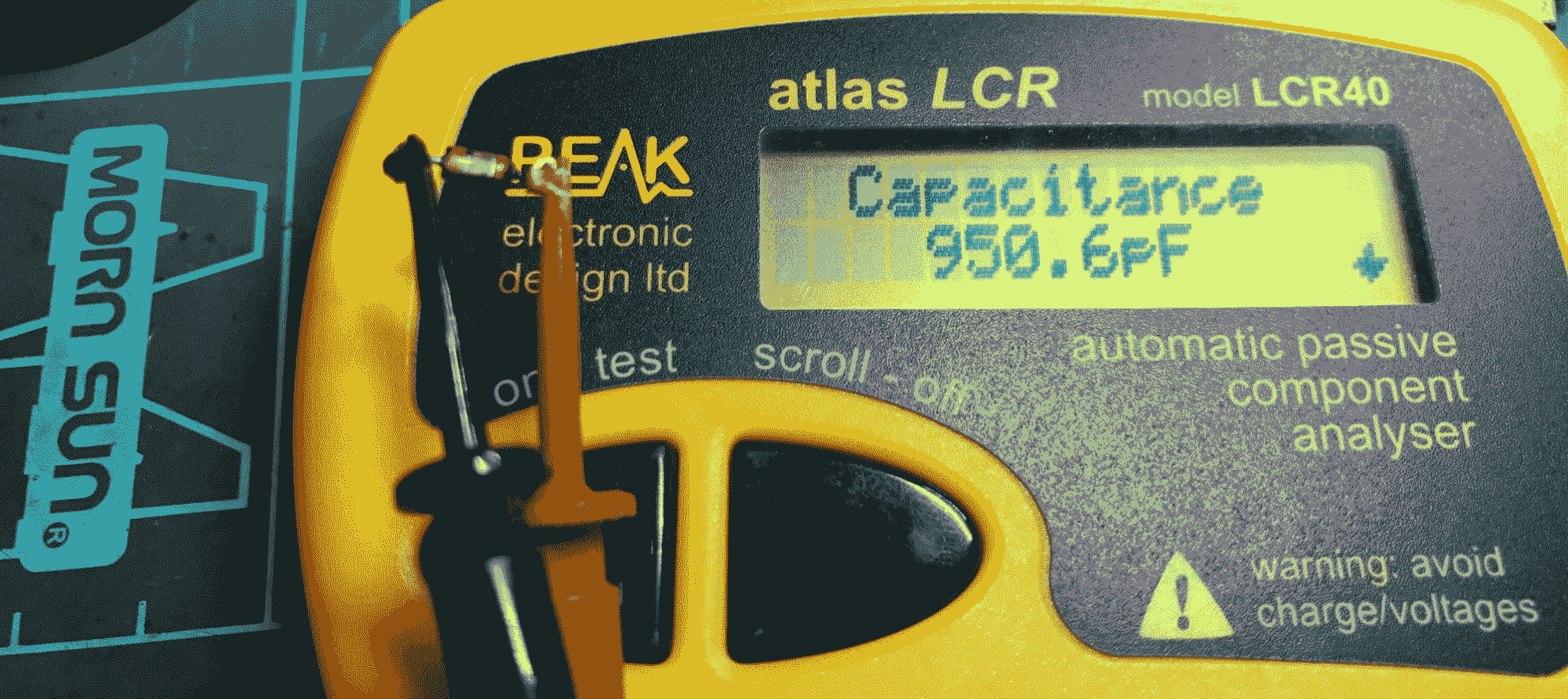
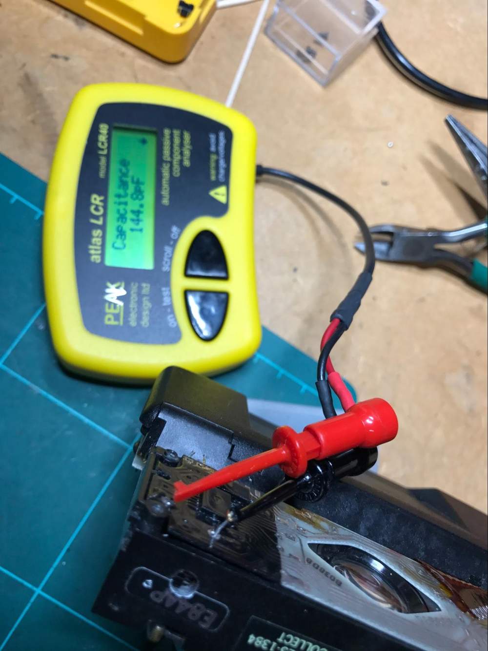
The capacitors are easy to source at an electronics store or website, but keep in mind to buy the smallest you can find. I have an assortment that makes it easy to choose the values I need to use “on the spot”. I also have a device to measure the value of the original component since the “black thing” used to “protect” the PCB makes it difficult to read the marks on the original component. I use PEAK atlas LCR model LCR40 as shown in this picture measuring my original capacitor.
As for the switch, this might be a bit more difficult to source, since it has to be really small to fit inside the SX-70. I got mine from RS COMPONENTS, but you will find them at Mouser, Farnell or maybe your local electronics store.
I searched for SMD SPDT sliding switch I got a few ones, some are too big, but also some are too small!
I finally used these from RS Components (search for “New Surface Mount Slide Switch SPDT Maintained 0.3 A Slide” RS part number 123-8926 manufacturer ALPS part: SSSS211603.
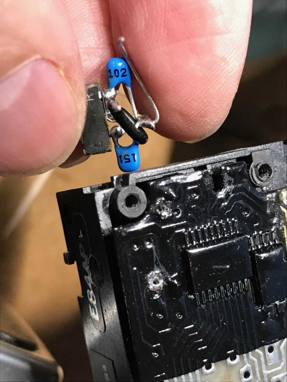
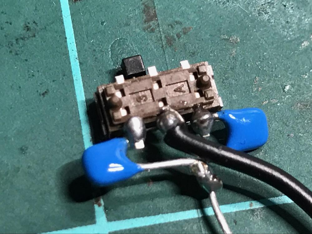
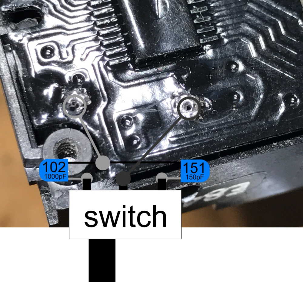
The wiring is simple: you connect one end of each capacitor to the pins on the sides of the switch and the other end of the capacitors together. The center pin of the connector goes to one of the original connections of the original cap, and the “common” of the caps to the other.
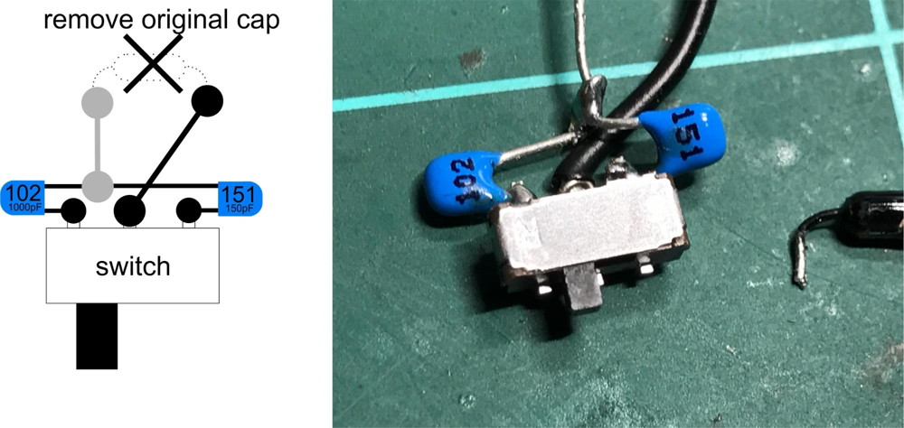
Here you can see some sort of schematic and the the “switch circuit combo” circuit ready for my Sonar. Keep in mind that the capacitor you are going to need for your camera can be different depending on your SX-70.
Step 2: Disassembly
This basic SX-70 dissasembly, I am going to detail on a Sonar, if you don’t have a Sonar it is going to be easier.
REMOVE THE SPREAD SYSTEM ASSEMBLY (FRONT COVER HINGE)
I usually remove this first. It is the “door” you open to put the film pack. You simply push inwards on one side and pull it out.
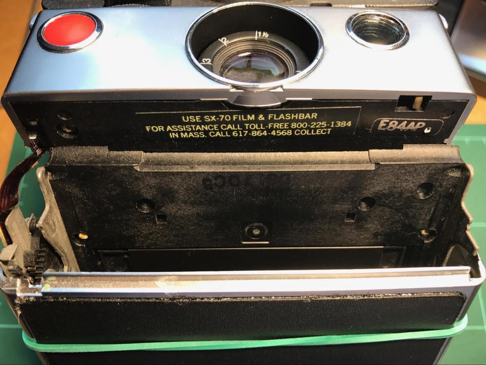
REMOVING THE UPPER HOUSING
I usually use a rubber band to retain the viewfinder cap. Then position the focus wheel to infinity and push the actuator button to its “automatic” position (making the wheel inaccesible).
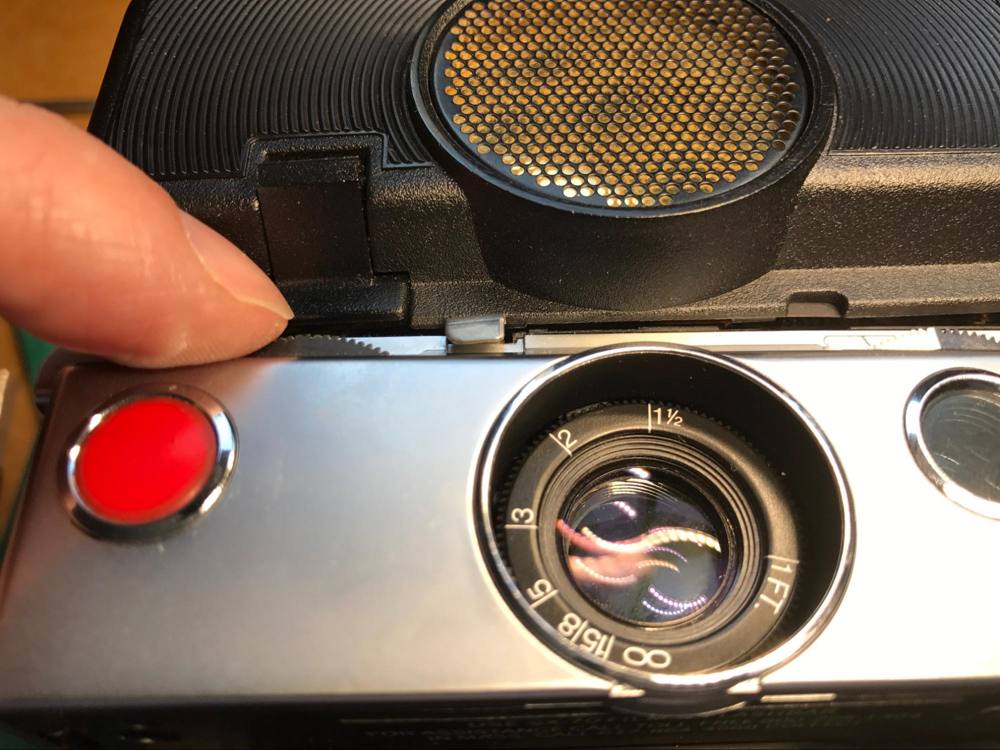
Using a prying tool I free first the tap on one side and then the other. Then you carefully push upwards to free the flash connector.
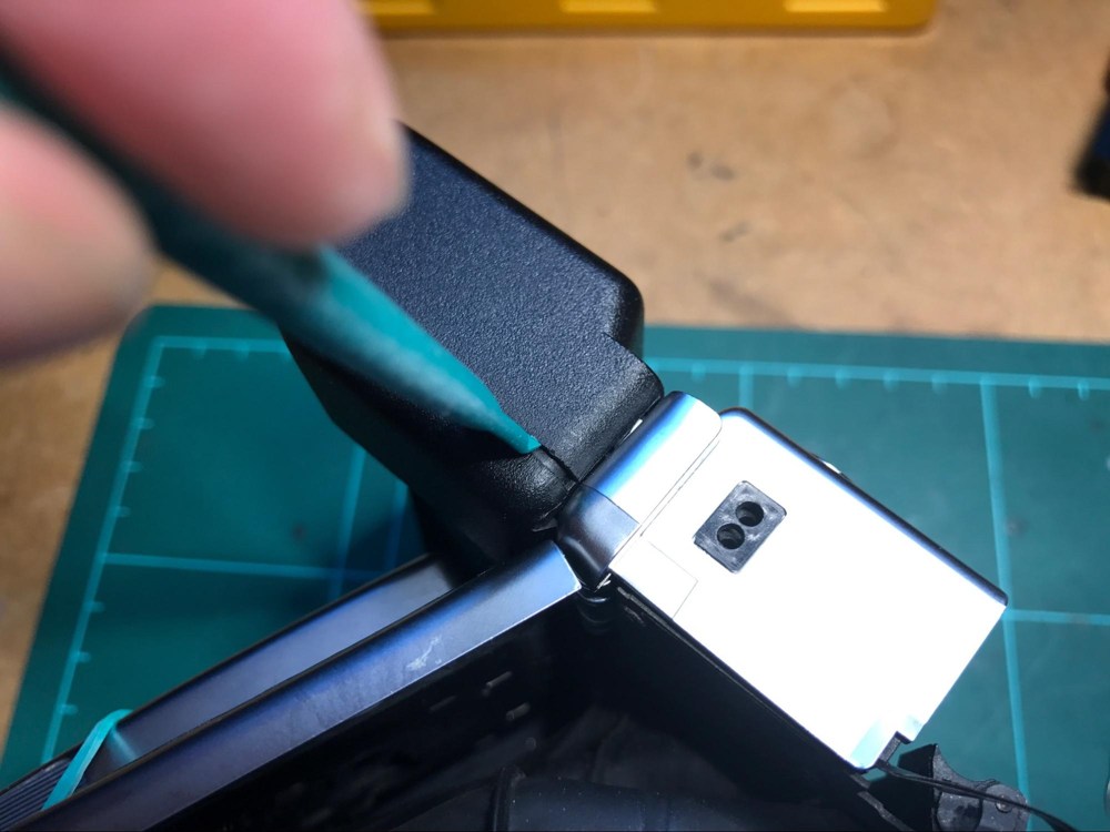
REMOVING SHUTTER FRONT HOUSING ASSEMBLY
Then you have to remover the cover of the shutter front housing assembly. I do it carefully pulling outwards from the side:
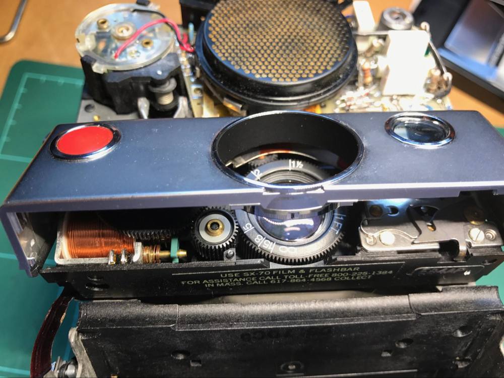
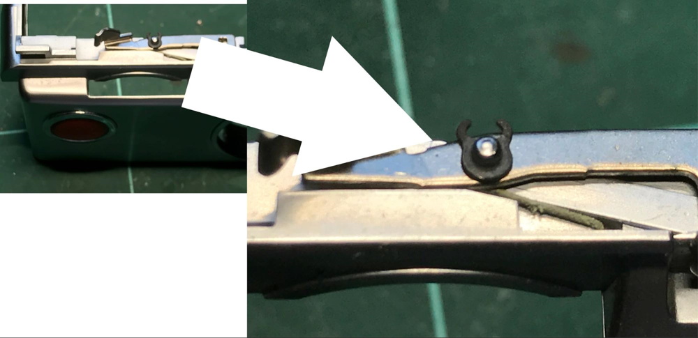
When you do that on Sonar be careful not to loose the retaining e-ring on the manual/automatic selector:
REMOVE THE SHUTTER ASSEMBLY RETAINING SCREWS
Now it’s the turn to use that fancy screwdriver that you got. WARNING: it is NOT advisable to use a normal (let’s say “any” kind of “normal”) screwdriver to remove those four screws (at least if they are of the 1mm x 1mm square special Polaroid kind).
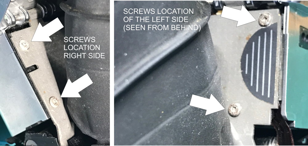
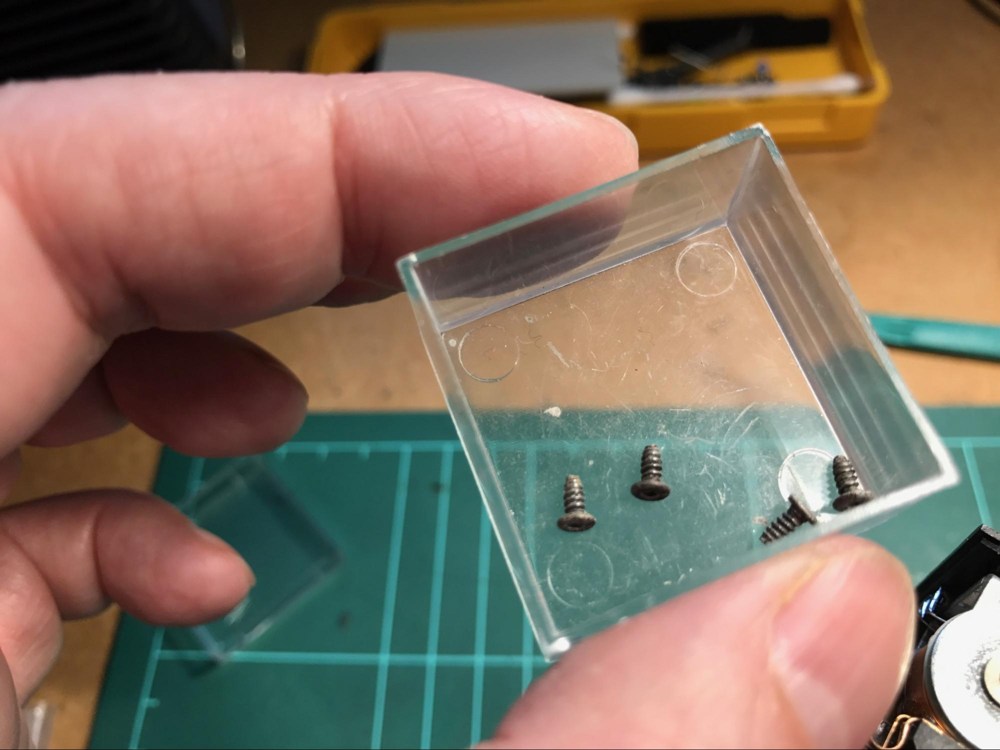
Store those screws in a safe location, these keep the light seal and you don’t want to have to mess with these on reassembly.
Step 3: Modification
SECURE THE “OPERATIONS” THEATER
At this point I usually use my vise to secure the whole thing since you don’t want to break or desolder/force the flex circuit. This is a flat cable circuit or, on older machines flat cables. These keep the shutter assembly tethered to the body of the camera.
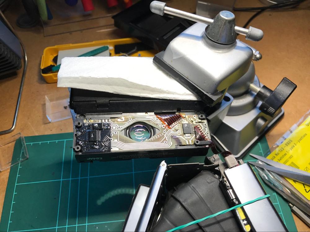
LET GET TO WORK!
Now you have two options: try to completely (more or less) remove the PCB from the housing. I tried that (I have done so in the past) or you can try to work around that and pull (very carefully!) the PCB up from the left (first remove the plastic retainer “thing” on the left.
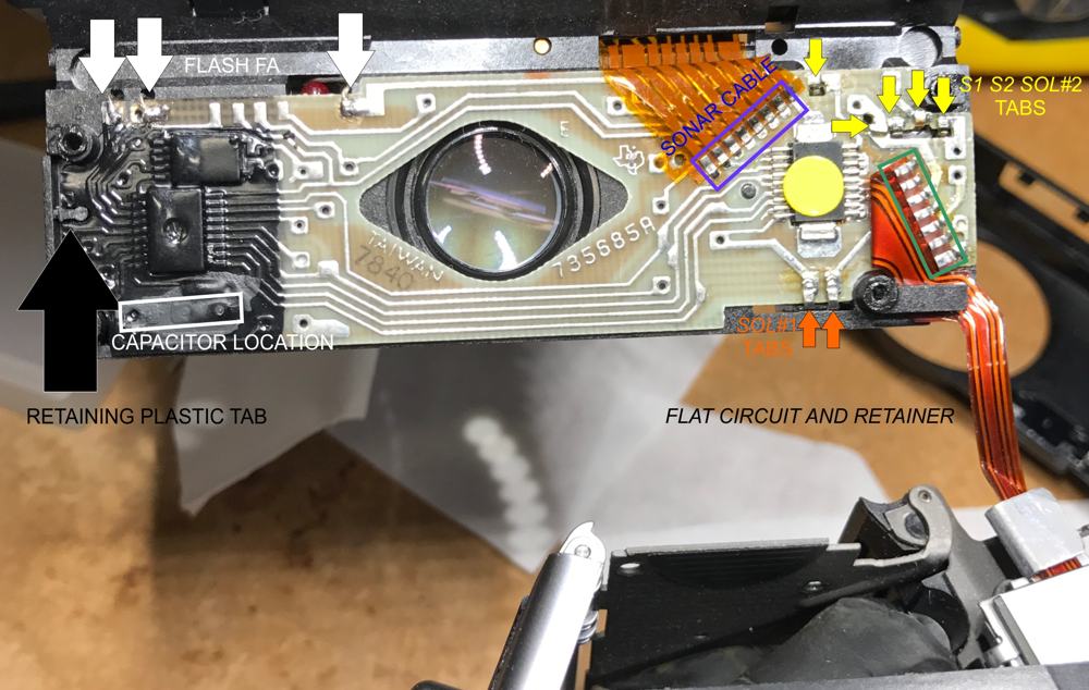
If you want to “free” the PCB (more or less) you have to very carefully unsolder the tabs connected to S1 and S2, SOL #1 and SOL #2 and probably both flat circuit cables one for to the camera body and (in the Sonar) to the sonar circuit.
Some cameras have four connections to the SOL #1. That is a delicate flat cable circuit so be careful.
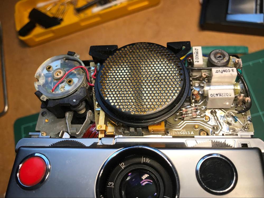
What I did actually is (I think) simpler, but might mean that is more difficulty installing the capacitor or the switch. I simply (and again, very carefully) pull the PCB:
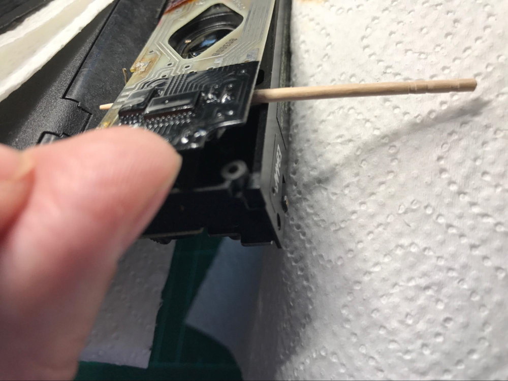
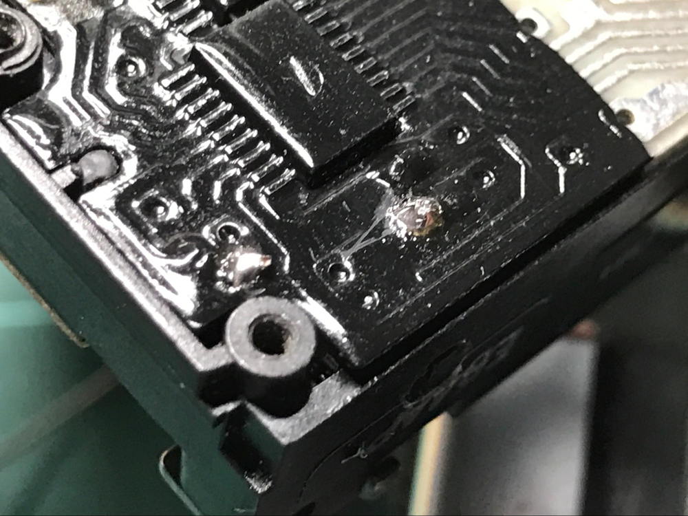
I then heat with the soldering iron the pins of the original capacitor and with a stick I pull it downwards loose. I heat with the iron directly on the black paint on top of the PCB and pull the cap downwards with a toothpick. Tests trying to remove the paint with solvent have been unsuccessful on my part. So I then end up with the original capacitor and measure it: 950pF:
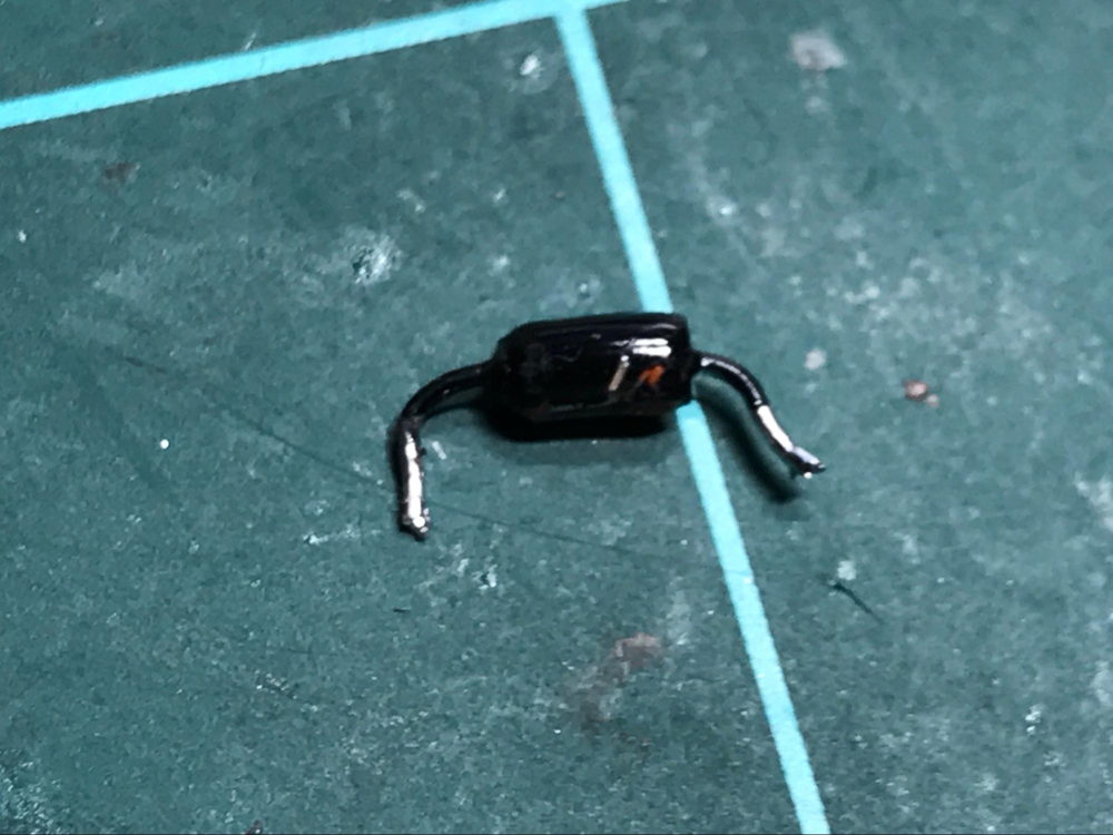
.
DRILLING THE HOLE
Under the PCB and roughly where the original capacitor is placed there is cavity. That is the place where we are going to place the switch.
In case you just want to to make a 100 to 600 conversion you can place the new capacitor and reassemble the camera. If your are having second thoughts about it is probably better to do just that. Anyway it is difficult to find a reason to shoot 100 if you can do 600 with an SX-70. In that case I usually put the new capacitor on the other side of the PCB, that makes it easier to change it for another value or whatever:
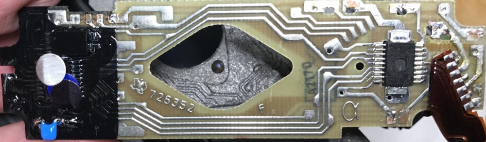
This is an F Alpha board with the “new” capacitor
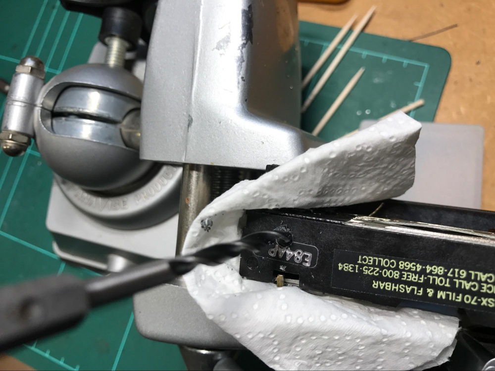
If you are brave enough to follow me, then it is time to drill the hole for the switch. I found that a wood 4mm drill bit is enough (but close) to operate the switch.
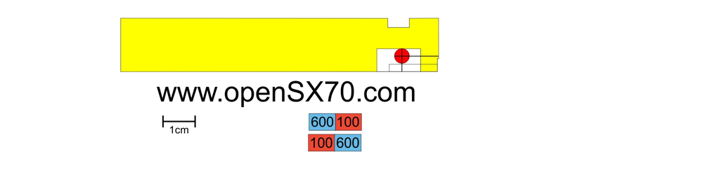
It is very important to do the hole in the right location, to not disrupt normal operation, so we end up in the aforementioned cavity. For that purpose I have made a template to locate the exact position.
Again a warning: please make sure that the template corresponds to your particular model of the SX-70 before trying anything, specially drilling a hole:
I cut the template (make sure the size is right) and put it on top of your SX-70:
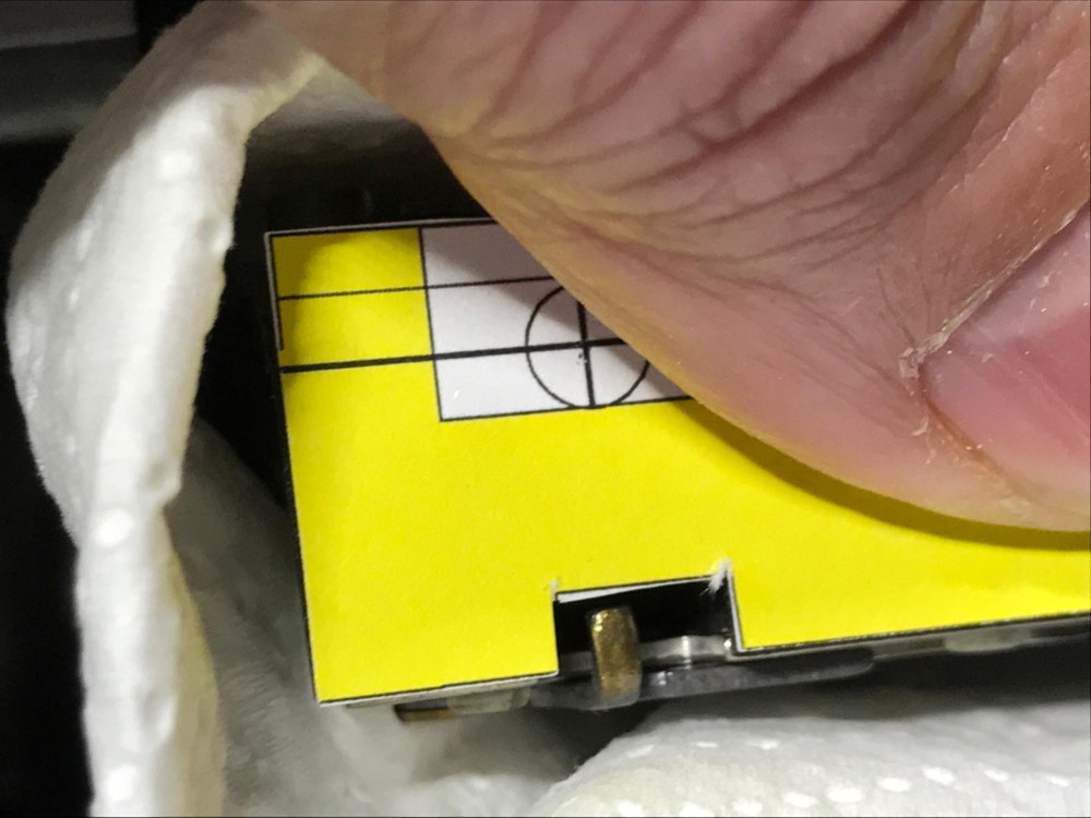
In the picture above in the right you can see from another SX70 the cavity where we intend to place the switch circuit combo. You have to drill at the right place up/down and left/right, and also that you can use the switch once the camera is fully assembled again.
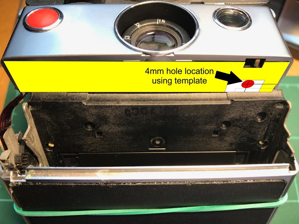
Then with a pin I mark the center of the (in the picture above the center of the red circle) and begin very very carefully. I clean the bit very often to avoid dirt to enter the camera or the lens. Perhaps it is wise to tape close the camera hole to avoid also contamination. I use the blower for this purpose.
Once finished (take your time) clean the hole and any dirt that might be around or inside the cavity. This is very important for the camera to take nice sharp pictures.
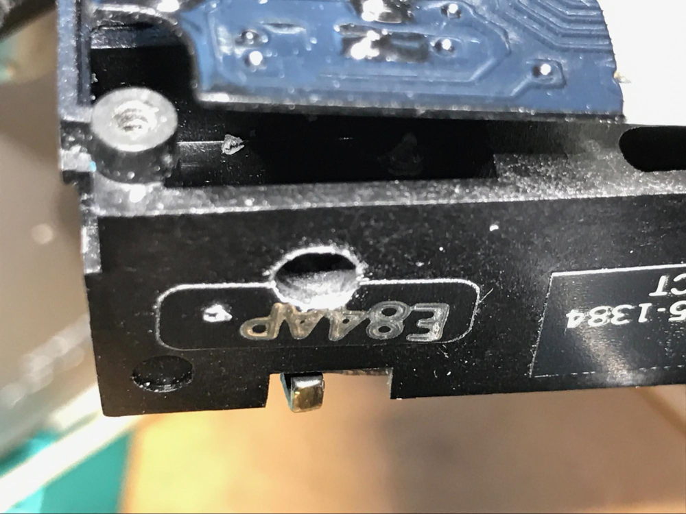
INSERTING THE SWITCH AND SECURING IT
Now it is time to carefully insert the switch in the cavity and try to pass through the holes in the PCB the cables. This step was for me the most difficult, and finally got it with a lot of trial and error.
I ended up inserting the switch combo upside down as it played better considering the depth of the hole:
Once the cables went through the hole of the original capacitor, I tested he operation of the switch (600 position):
So once you are 100 sure you glue the switch just enough, in my case I used C9 (compound 9) knowing that if it didn’t work I could very easily remove it. I guess that using some other kind of glue or epoxi is just fine.
SOLDERING THE SWITCH
Then finally you press down the PCB and solder both wires (and test again).
Just soldered, nice and shiny.
Just to make sure these are the connections overlaid on the other side of the PCB (the switch goes underneath of the PCB):
Step 4: Reassembly
Now you are almost there, so a bit of patience. It is time to assemble the camera. If you took out the PCB make sure that you connect and solder all the tabs, cables and stuff you took away. Make sure that you insert the flat circuit that connects to the body of the camera in the retainer tab, because once you have soldered it it is almost impossible to do so.
Double check every step as an error here would set you back later, having to disassemble again.
Be also very careful with the boot or plastic bellows to avoid damaging it. If you puncture it, then it is game over for that camera.
Make sure that the screws are reasonably tight to avoid light leaks, but don’t over do it at the ristk of damaging the camera, snug, but not too tight. No excessive force needed.
Step 5: Finishing touches
I printed the template for the hole on a piece of adhesive paper. If you notice there you can cut from there the indicator you need (depends on how you placed your capacitors). You can also make your own. This for me was the final touch.
Final thoughts: I am thinking now on how to improve the process. May a very small PCB with SMD capacitors and the switch be a better solution? Then very thin cables to the SX-70 board, to avoid possible mechanical tension.
If someone knows of a better, simpler or faster way of doing this, and wants to share let me know.
Also if you know of a better source for the tools I would also appreciate the information.
I am always looking for SX-70-related tools or detailed pictures of those tools. Those would be very much appreciated.
Any error or improvement/suggestion on these texts, pictures and tutorial will also be appreciated.
Will post some sample shots ISO 120 and 600 soon!
Tutorial by Joaquín de Prada/Version 1.6 04/17/2017
APPENDIX
http://www.sx70store.com/tienda/reparacion-y-mantenimiento/conversion-a-600-sx70-detalle.html
https://www.2ndshotsx70.com/repairs
I don’t know if MiNT camera in Hong Kong will do the modification, but they have the amazing SLR-670 in their different versions, and that is the most awesome (sorry for the word) SX-70 ever.
https://mint-camera.com/en/polaroid-sx70/repair/
Finally here is a table with my results and some from the Internet to help you choose the value for your capacitor.
| Serial | Type | Board type | Original Cap | New Cap | Comment |
|---|---|---|---|---|---|
| 680pF 200V | 150pF 50V | ||||
| 5D940853525 | Sonar OneStep | 1100pF | 270pF | ||
| Sonar OneStep | 1024pF | 150pF | |||
| 746pF | 150-180pF | ||||
| 680pF | 180pF | ||||
| 920pf | 150pf | ||||
| G706431 | 1000pf | 220pF | OverExposing: better: 180pF or 150pF |
||
| 5M849352085 | Sonar | F726352 | 150pF | Killed the original cap | |
| 5G843113652 | Sonar | E735685A | 950pF | 150pF | dual conversion |
Comments