OpenSX70/Arduino for Dummies (part 1)
Introduction
Some people think that I know electronics, well, the truth is that I actually don’t. I studied law in college. So everything I say from here on is probably “wrong” you have been warned.
Nevertheless I am going to try to explain to you the basic principles of how I have been able to fake my way in the openSX70 project. Most of it is copying and pasting!
That doesn’t mean any disrespect for the electrical and the electronic engineers, on the contrary: I truly wish I could have studied to be an engineer!
I mostly Google stuff that I want to figure out, but there are two book (they are also in PDF) that have been essential to me, one for hardware and another for software:
ABC Arduino basic connections by Alberto Piganti, I actually got the original physical book, it is like a bible for me, but at the same time it reminds the kids ABC books: very simple. I bought it at the original campaign he goes by PighiXXX and there seems to be a much better new version this is the website http://www.pighixxx.net.
The second book is about software for the Arduino. It is “Arduino Programming Notebook” by Brian W. Evans. It is the same concept, very simple and hands-on.
It is also important to note, that there are many companies like Sparkfun and Adafruit (and probably many more) that have all their amazing designs as open hardware, so you can not only download the schematic PDF but the EagleCAD files that you can open and edit and modify. I have used this for the FTDI only, the arduino part I did from scratch, although there were probably a few examples that I could have used. For the uDongle I had to do it from the datasheet of the Dallas Semiconductor DS2408 chip, and that is indeed the final source of amazing and free information: the datasheets of the electronic parts. Some seem a bit daunting, but, if you stick to what you actually need and prescind of all the rest you will be fine. Mostly I use them for the “reference designs” examples or whatever they call them. This is an example, and although maybe is not exactly what you need, it is close enough and easy to adapt.
Speaking of electronic components (since I have mostly no idea of what I do) it is hard for me to find the “right” component. So many times I end up buying a few different ones, and then testing the better suited. I usually get my components from Farnell or RS Components, although I find myself lately buying some of the components in EBAY.
I guess there are two very important things regarding electronic components: first you want something “current” in the sense that you don’t want to use a component that is a)obsolete and thus b)expensive and hard to find. Second I guess that you want to choose the cheaper component, sometimes the components have stricter tolerances or whatnot and that makes them more expensive. I really don’t care much about that right now. Some chips like the FT232RL are quite expensive, and, what is really troublesome there are a counterfeit chips that don’t work!
Also, when you want to have your stuff professionally manufactured, like I do with SeeedStudio Fusion and their PCBA (PCB assembly service) you want to use the parts that they either already have (they have a list called OPL) or that they can get. This service is so amazing that you just upload the gerber files (those are like the PDF files of the printed circuit boards world) and what is called the BOM (Bill of Materials), you pay them and (hopefully) in less than a month you have your circuits: Amazing!
Schematic
So here is the Pathfinder schematic, you can find the true Eagle file in Github.
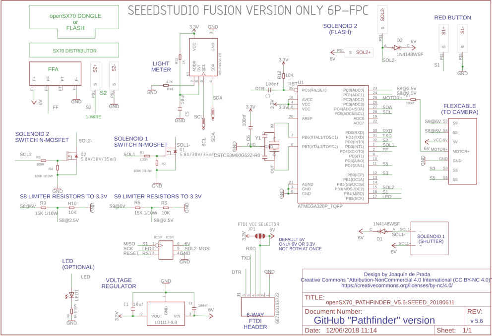
I call it the SEEEDSTUDIO FUSION 6P FPC because I modified my original design to parts friendly to Seeed. It is 6P because the flat cable and connector has 6 ways, maybe I didn’t need them all but it is more compatible with the 6-way FTDI headers. Actually, if you have a cable adapter you could use any FTDI from Sparkfun or whatever.
As for the PCB (printed circuit board) I will delineate the different components from the schematic:
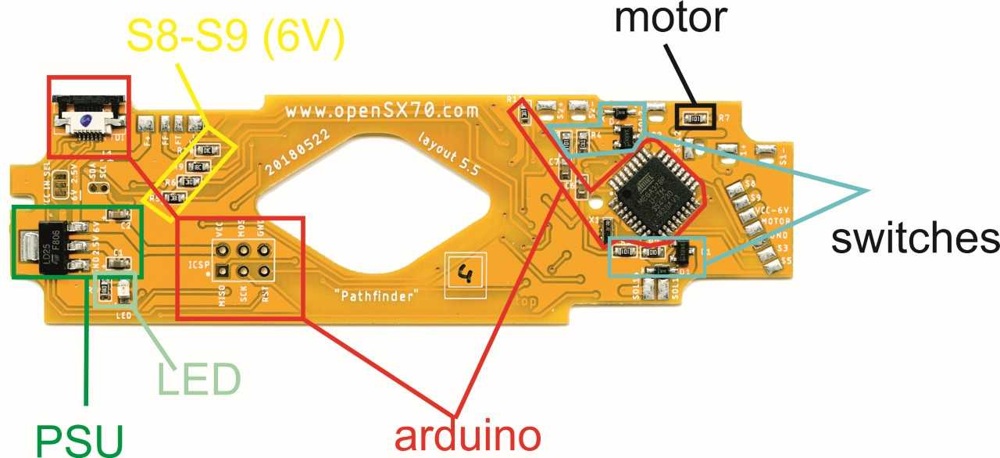
So here you have PSU, power, more like a stepdown transformer in green, the Arduino part, in red: basically two connectors, one with the flat cable FPC for the FTDI (read USB adapter) and ICSP. Then in sort of blue are two electronic switches for each solenoid, in black there is a resistor that is in between the arduino output and the electronic switch for the motor already in the camera. the yellow part are voltage dividers, needed to bring down the 6V coming from S8 and S9 in the camera. In a light green there is the LED. That could be considered part of the arduino.
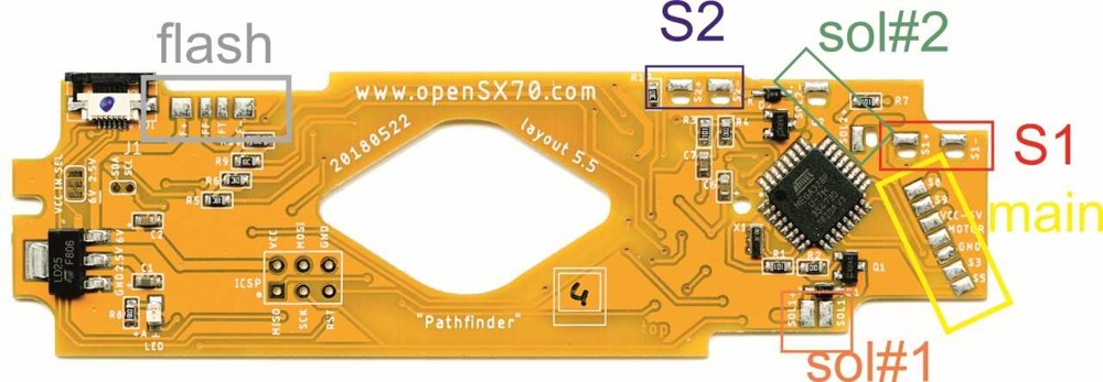
Here we have the SX70-related connector or header or whatever, these correspond to what is already in the original substrate or ECM. The Flash header or FFA in grey that has 4 connectors F+ (that is 6V) and F- (GND) and then FF (flash fire) and FT (Flash Trigger?) that last one is not connected in the openSX70 camera. In yellow you have the main connector to the body of the camera. Here come the “state” of the switches, S8 and S9 (nothing or 6V) also S3 and S5 (to GND) and VCC and GND (6V coming in from the pack) Motor just turns on the motor through the electronic switch on the camera. S2 in blue just signals when there is flash inserted, circuit open when not and closed when there is a flash. Solenoid #1 in orange is the shutter, and solenoid #2 is related to the aperture at close range when using flash. Finally, in red, how else is S1, that connects to the red button.
power
There are few things you should, but this is one of them, first, there two types of electricity or power AC (like 220V or 110V at home) and DC or Direct Current. First DC has polarity, like a plus (+) and a minus (-), plus is usually called VCC or just indicating the voltage, for instance in the SX70 camera the power comes from the battery on the film pack. It is 6V. And then there is the negative that is called GND.
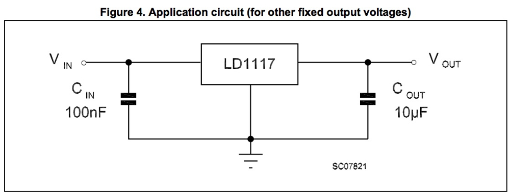
The first chip we need in the openSX70 circuit is the regulator, we have to “step-down” the 6V to something that the arduino likes better, that could be 5V, 3.3V or even (as we actually do) 2.5V. The chip we use for that is called a “regulator” and in our case it is LD1117-25. The last two numbers indicate the voltage, there are for different voltages. Also if you are curious enough to check the datasheeet you will notice that it comes in different shapes or forms, those are called packages. In my mind there are two kinds of componets: old-fashion and usually quite big through-hole, and smaller SMD or surface mount. I needed the smallest I could get so I went for the SOT223. It has 3 pins: one is GND, the other is the input voltage from the camera (6V) and the other is the output desired voltage (2.5V).
On page 8, figure 4 you have the circuit I use.
I will try to explain a bit why we need 2.5V to run the Arduino. Why do we have to have two different voltages? My main original idea was to stick to something as close as possible to the original voltage, that way everything would be much smoother: Right? WRONG!!!
One basic rule when you have a circuit dealing with different voltages is that the GND or negative is always interconnected. This is important. Then you have your positive 6V and your positive 2.5V. But all the GND is the same! This is important and has its consequences later.
Think of pipes: the higher the voltage the wider the pipe. Might be easier to understand if you think of the circuit as pipes and think of the stuff you do with that current as, lets say, wheels that spin by the water on those pipes. We need the wheels to always have movement. If they stop the camera resets or whatever goes wrong. But sometimes we need to be doing quite a lot of stuff at the same time: moving the rollers, taking the pictures (solenoid #1) firing the flash… whatever, AND at the same time the arduino microcontroller needs enough power to keep or running. That is why the smaller are the pipes the more “pressure” will have the water, thus never dropping pressure.
That is why after quite some experimentation and the help from my friend Peter (he really knows his electronics) we run the arduino at the measly 2.5V. That, of course, means that the wheel cannot run very fast, instead of the “optimal” 16mhz the microcontroller can handle, we run at 8mhz, which, mind you, is more that enough for the SX70: the important part is that the “show” never stops, or, in other words, the microcontroller never resets.
So the circuit has the regulator and then two capacitors. This is determined by the manufacturer of the chip. They have a “reference” design, and, in this case, this is what we have.
Now we have two voltages: 6V for everything SX70 related, she, still needs what she needs, and our 2.5V for the “Arduino part”.
Arduino
So in an Arduino-based circuit one would guess that we need an Arduino: yes we do. As a matter of fact I started with an actual arduino board, but now, I have the Arduino embeded in the main PCB.
Now let me explain what is an arduino. In simple words it is a computer, in its simplest form, it is a microcontroller (in our case an Atmega328P) and a few components. But much fewer components that you would think.
What makes the Arduino special is that it lets you interact with the physical world. Like if you flick a switch something happens, a LED lights, or blinks. So you can detect if a wire is connected (to VCC or GND) and it can “turn on” things, not “big” things but rather low-current things, like an LED.
So it’s most basic program, the Arduino “blinks”, that is turns an LED, waits and turns of the LED.
What I needed was the simplest form of Atmega328P-based arduino. I mean really really the minimum. So I googled it.
You find many many (mainly images) like this one:
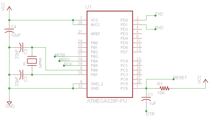
Turns out that an arduino is quite simple: you need the microcontroller, in our case it is Atmega328P, two capacitors and a resitor. And of course a resonator. This a clock, and two capacitors. It comes in a package so you don’t have to deal with three parts but one. The crystal is vital as it is what sets the speed of the microcontroller. In our case 8mhz.
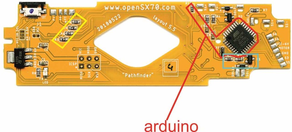
You can see in the red outline all the main components, R12, C6 and C7 and of course the resonator with the crystal X1. The big chip is the Atmega328P mentioned before.
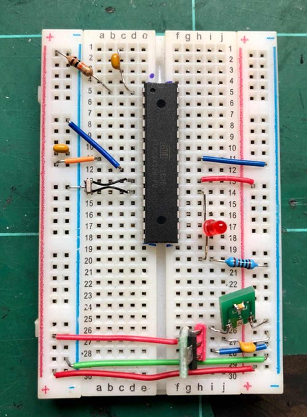
What I try to always do is to test the circuit with breadboard. Here is my barebones Arduino, with the “minimum components”. The package of the Atmega328P is DIL (through hole) to simplify.
First the datasheet, as you can see it has 442 pages!!! So I checked for the different packages.
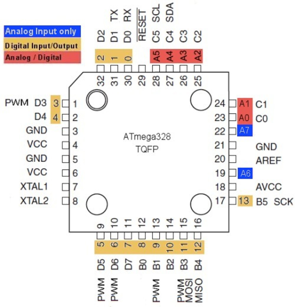
The picture comes from here
I finally settled for the TQFP package, not the (even smaller) VQFN or MLF, in part because if what I want is to have the PCB manufactured but hand-building the prototype, that kind of packages is almos impossible to do by hand (maybe on the reflow oven, but I don’t use it that much).
What makes an Arduino an Arduino?
That is a good question.
You are probably better reading some of the answers in the internet, like Sparkfuns, but in the end we basically all agree that is physical computing, thus, we make things happen, turn on motors, solenoid, and get information from switches. It is open source, it uses the Arduino IDE development enviroment. It is very easy to program via USB, you don’t need, in principle any special programmer or anything. That is because the arduino has pre-loaded a small program that facilitates all that: the bootloader. One could say that the bootloader is somehow openSX70s “secret sauce”, it might be, it has been custom made for me by my friend Peter and has some special characteristics that make it reliable and suitable. Not rocket science, but very important. It is based on the optiBoot bootloader.
Of course the other essential component of an Arduino is more part of the microcontroller: a bunch on general input output ports (GPIOS) to interact with the physical world.
In the next part I will explain about the SX70-specific circuitry and how I implemented and tested that in the FrankenSX70 camera.
Comments