KEEP OUT!!
Things are busy in the openSX70 lab! A lot of news at the hardware and software fronts. Firstly and as previously reported the latest PCB that I had “chocolate” works and can control the SX70. It can close and open the shutter and drive the mirror up and down.
HIGH VOLTAGE
For that purpose the circuit uses a regulator to bring down the incoming 6V from the filmpack battery to a more friendly to the microcontroller and stable voltage.
The problem was that the moment the motor and shutter were active the power drop caused a reset of the circuit. So initially I went to 3.3V and run the microcontroller at 16Mhz, but finally will probably settle at 2.5V and 8Mhz. You might think that running the circuit at a lower is somehow wasteful of the precious power from the filmpack battery.
Turns out it is not. That gave me a very stable current for the microcontroller and that is good. But that small (in my mind) change in the regulator had unforeseen consequences for the dongle (more later).
So having the circuit and PCB design (“chocolate”) basically validated I decided right away to design a new board.
The program beeps with the built-in buzzer once and runs shutter operation only (notice the resonance when the shutter is closed, that is the camera solenoid and need to be fixed!) then it beeps twice and runs the motor mirror-up/mirror-down sequence, and then beeps three times and an simulates the whole thing, that is, taking a picture: shutter-close/mirror-up/quick shutter open-close/mirror-down/shutter-open. That means that is capable of doing the whole sequence!
MISTAKES
The change on the regulator chip which has exactly the same form factor, in my ignorance, I though would be straight, but it was not to be, as you will see. Let’s get into themistakes that I had made and als some improvements I wanted to make.
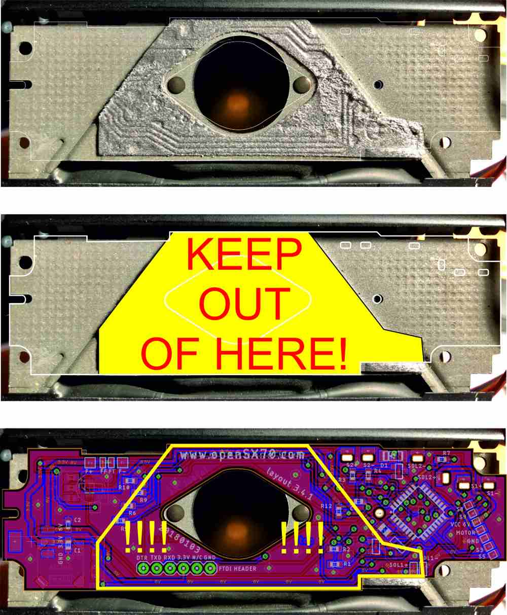 You can see the actual light-seal on the camera, then the yellow-keep-out-area and then that “chocolate” had a bunch of stuff in there.
Firstly that I connected solenoid #1 (shutter) to input 5 of the Arduino instead of input 3 as I intended. The way the Atmega328P works makes it more convenient to use inputs 3 and 11 for the solenoids. The reason being that this error makes the camera do a funny noise or resonance when taking a picture because I am using PWM to bring power consumption down.
The second and most embarrassing that I “forgot” that there is a light seal on the camera and I should keep my electronics out of that area.
NEW PCBs
I have ordered new PCBs, all kinds of PCBs: New main PCB (I called this new board design “Aladdin” and it is an evolution of my previous design), new Dongles (that is due to the power issue I mention are going to be useless) and a new custom board for my TQFP adapter so that I can program the bootloader with the minipro.
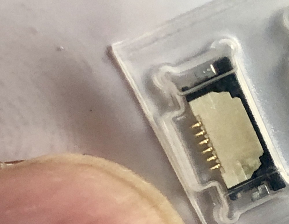
I have two flavor of “Aladdin” one with the FPC and one with the same connector as “chocolate”.
I also have done a custom FTDI board based on the basic Sparkfun one, that connect to my FPC cable as I mention next.
But then I thought about the programming and updating of the camera: Having abandoned the idea of programming the arduino via the flash connector (I don’t know how to do that) I figured that during development and calibration I would need to reprogram many many times. So I thought of using one of those flat cables.
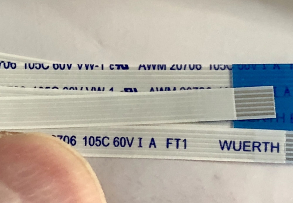
This cable is similar to the flat cables that Polaroid used to connect the front and the back of the camera or the shutter to the sonar but much more narrower, it runs 6 lines and is 5mm of width!
ABOUT A DONGLE
So I decided, thanks to my friend Peter to go down to 2.5V/8mhz. Same form factor chip. Easy! I get the new chip and just exchange one for the other. I check basic functionality: everything works. Then I test the dongle: NO DICE, doesn’t work!
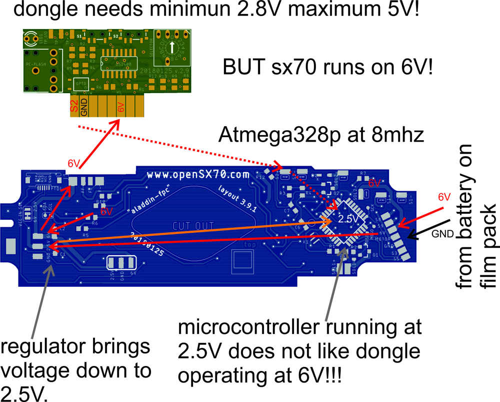
Making a long story short, there are basically three voltages in the system:
- SX70 battery = 6V
- Atmega328/Arduino = 2.5V
- DS2408 on dongle = 2.8V - 5V
But since I am feeding the dongle with 6V from the battery, I was sending back to the Atmega 6V, that worked (miracously) at 3.3V but not at all at 2.5V (maximun would be 3V).
That is why I have to make a new Dongle board including a 2.8V regulator to bring the voltage way down on the dongle, and stay within the 3V that the atmega expects.
So the dongle boards coming are useless.
NEW OPENSX70 SUPPLIER
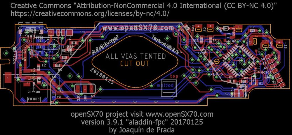
I want to talk about the boards. I used to get the boards from OSHpark. I love their quality and price. Unfortunately I cannot source my boards from them anymore. The reason being that I need the main PCB of a .6mm width and the dongle of 1mm. OSHpark only does .8 and 1.6mm I think. So now I source my board from the awesome guys from JLCPCB. They manufacture cheap, amazing quality and really really fast, and believe me, when you send your design to manufacture you want the results fast! This are the gerber files:
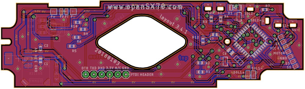
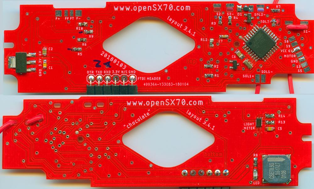 (the red “chocolate” boards already manufactured by JLCPCB, the new “Aladdin” PCB will be blue)
Disclaimer: I get no endorsement nor perk from neither OSHpark nor JLCPCB!
I want to thank again my friend Peter for all the help and support, without which, this project would not be possible!
#openSX70 #SX70 #Polaroid Originals #OriginalPolaroids #Polaroid #Arduino #JLCPCB #DIY
Comments