the picture as a voltage drop
So Dave was thinking we should go back to 3.3V from 2.5V (and he seems to be right). So we measured the voltage drop from the battery on an original camera. This corresponds in layman’s words to how much power is consumed by the camera during operation. We had run these tests in the past but with a major flaw. We used then wires that were both too long and to thin.
So here we are again repeating them (sorry for the vertical video):
What amazed me from the oscilloscope trace is that you could clearly see all the different operations (see the sequence at the bottom of this post) of the camera from the power consumption. Let me try to explain to you with pictures.
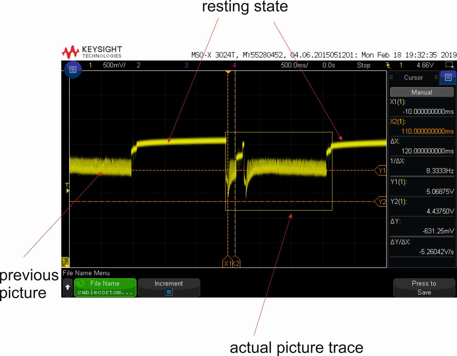
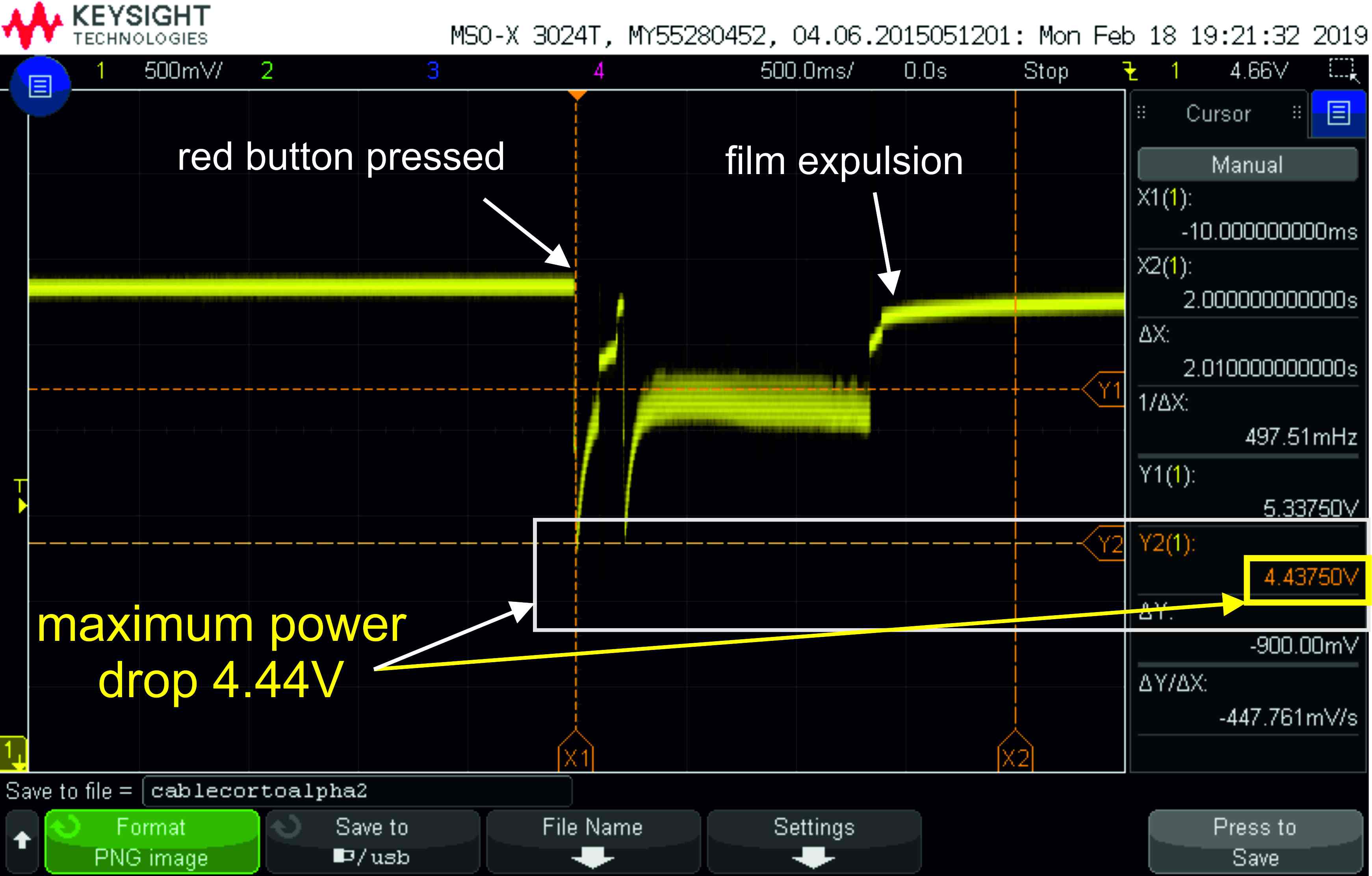
In the first image we see traces of two picture-taking operations, so you see the idle state and in the yellow box the actual picture taking.
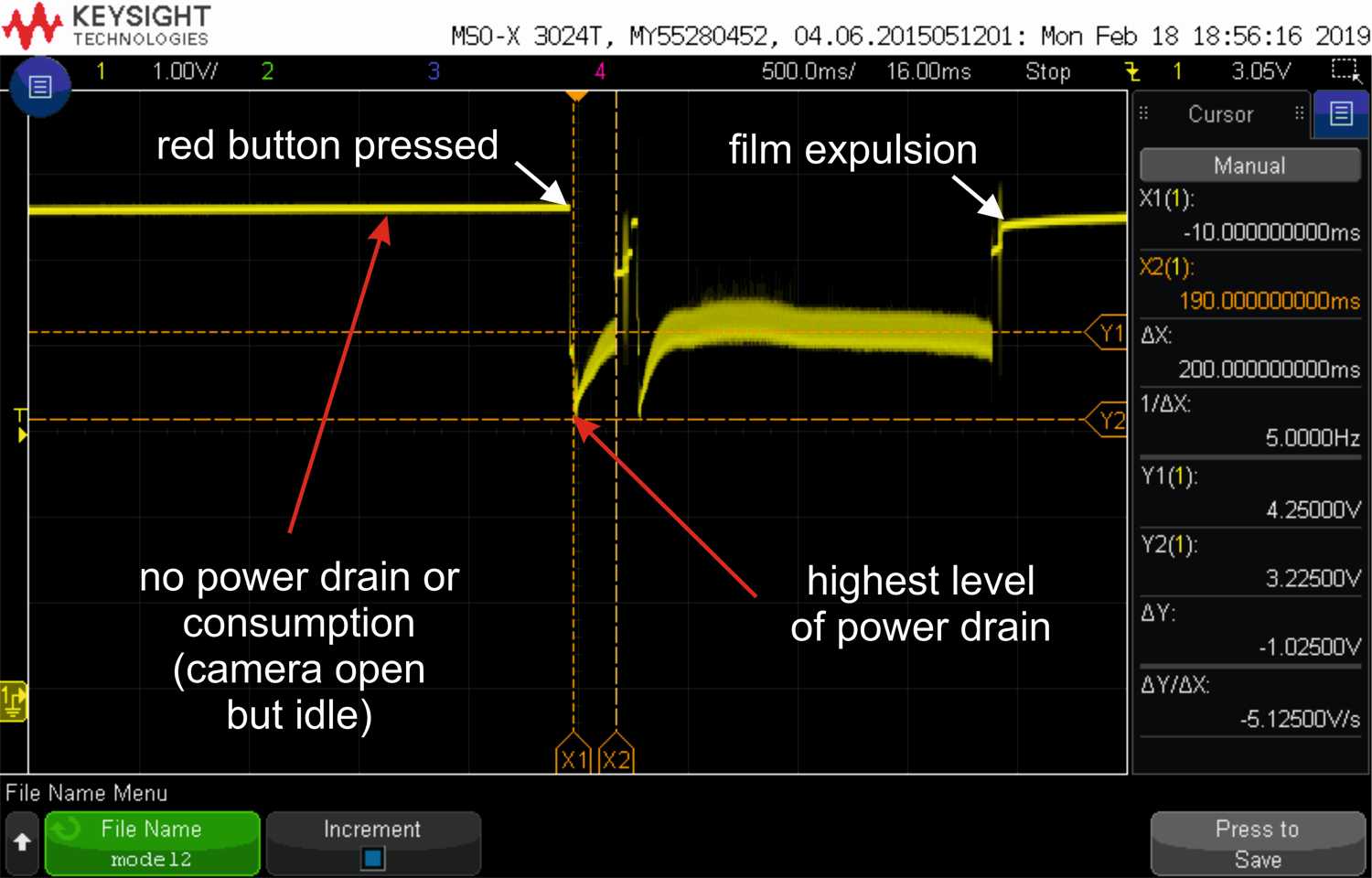 The line traces time horizontally. We see no power drain when idle, and things happening when we press the red button. The lower the trace the more power consumption there is.
 So need to know a few things. Solenoid 1 is the electromagnet that actually moves the shutter. When we feed no current, then the shutter is open. When we feed the 6V then it closes. Simple?
Well, not that fast: Polaroid engineers in the 1960s found that it drained so much current, that they didn’t have enough to keep the electronics running. And that was a big problem! (I highly recommend reading “The Battle for the SX-70” (electronics) by Tekla S. Perry, pusblished on the IEEE Spectrum Magazine in May 1989) So they came up with a solution. YES we need a lot of power to actually move the shutter to close position. BUT once its there we just have to keep it open, and much less power is necessary. Hence the “POWER-UP” mode and “POWER-DOWN” mode. Keep in mind that power down doesn’t mean NO POWER, but a power-saving state. This can be seen in the camera operation sequence from Polaroid (transfered to a more readable spreadsheet by me).
In early cameras I think they did this mechanically. S4 works as a sort of mechanical relay from AC position to BC. I assume some sort of power-limiter (a resistor?) was used in BC position. Later cameras (ALPHAs on) only have two connections and no S4.
So let’s see in detail the actual picture-taking process
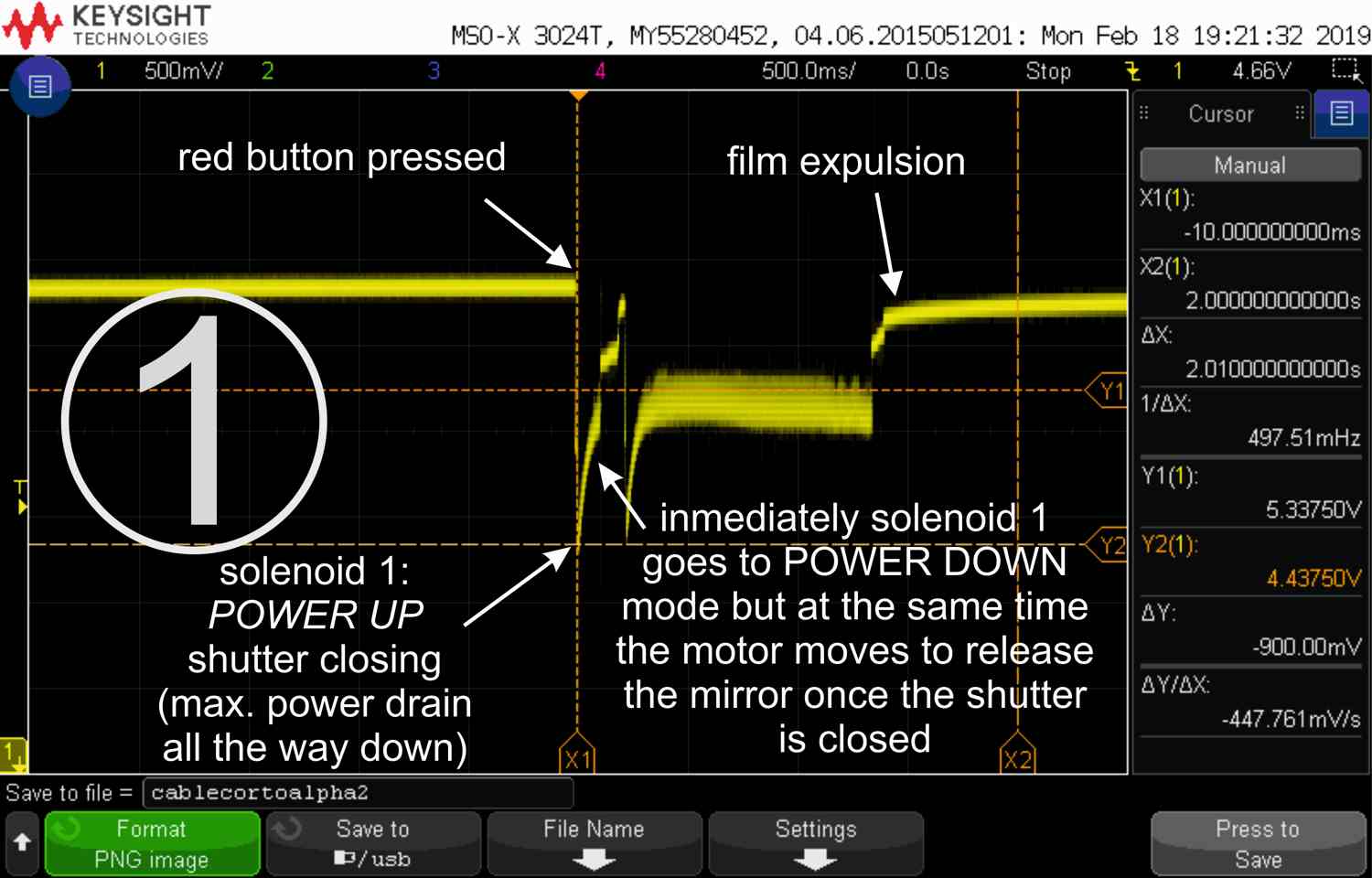 (1)Maximum power drain inmediately after pressing the shutter button, but it barely peaks and goes to power-down mode while running the motor enough to bring the mirror up (it is like a trebuchet with a spring that is released).
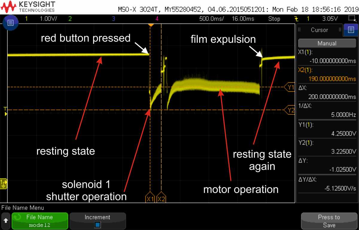
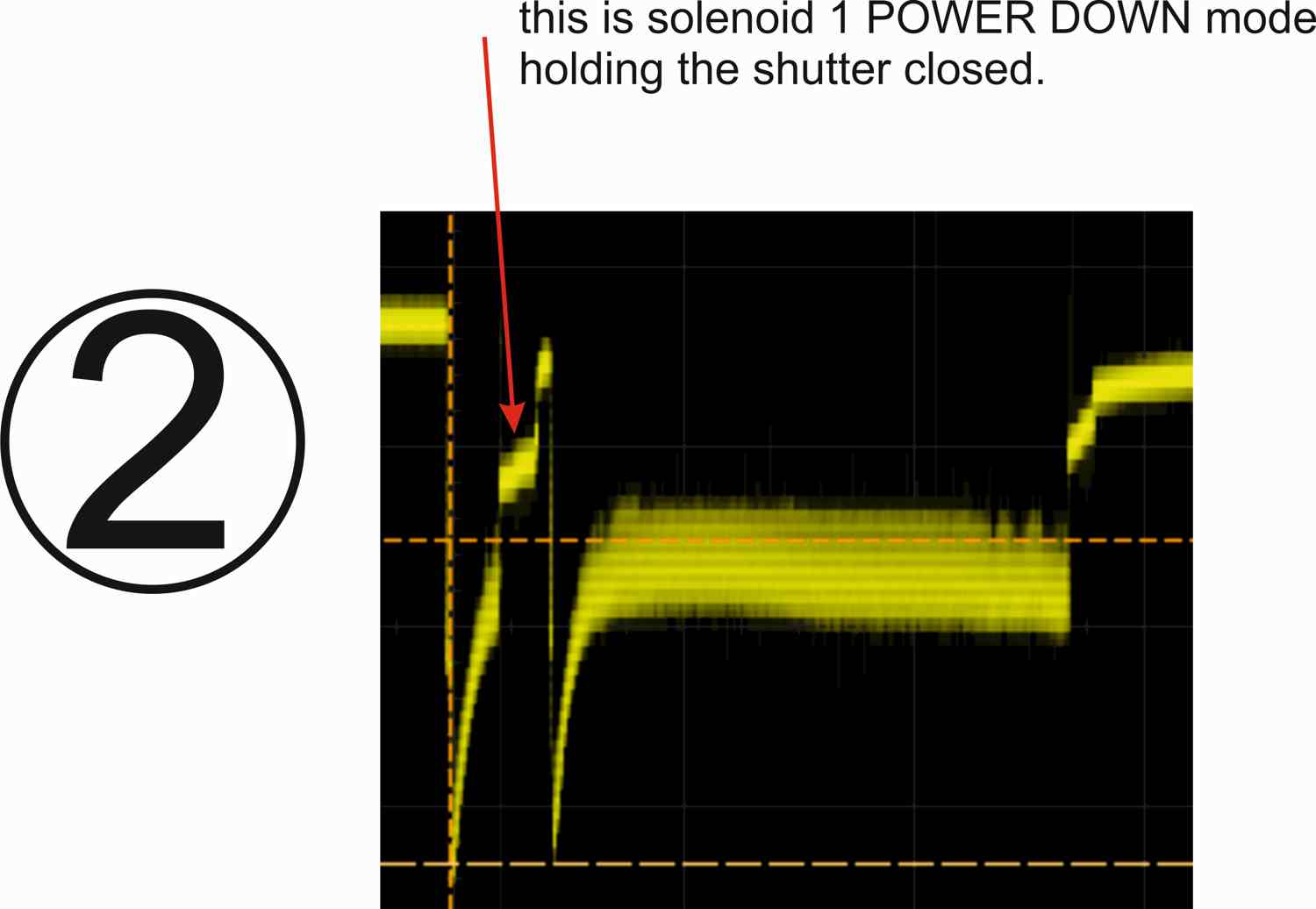 (2) Here we see in detail that the motor has stopped but the shutter remains closed.
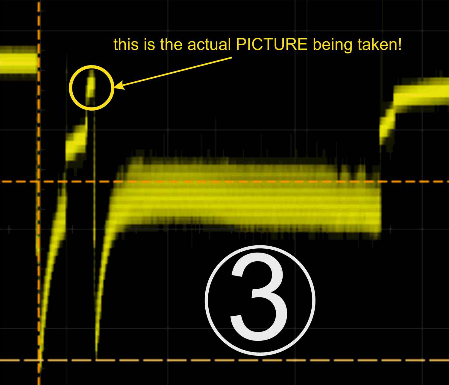 (3) Click! we have a picture. Remember, when the shutter is open the solenoid has no power (it is his idle state for focusing and all).
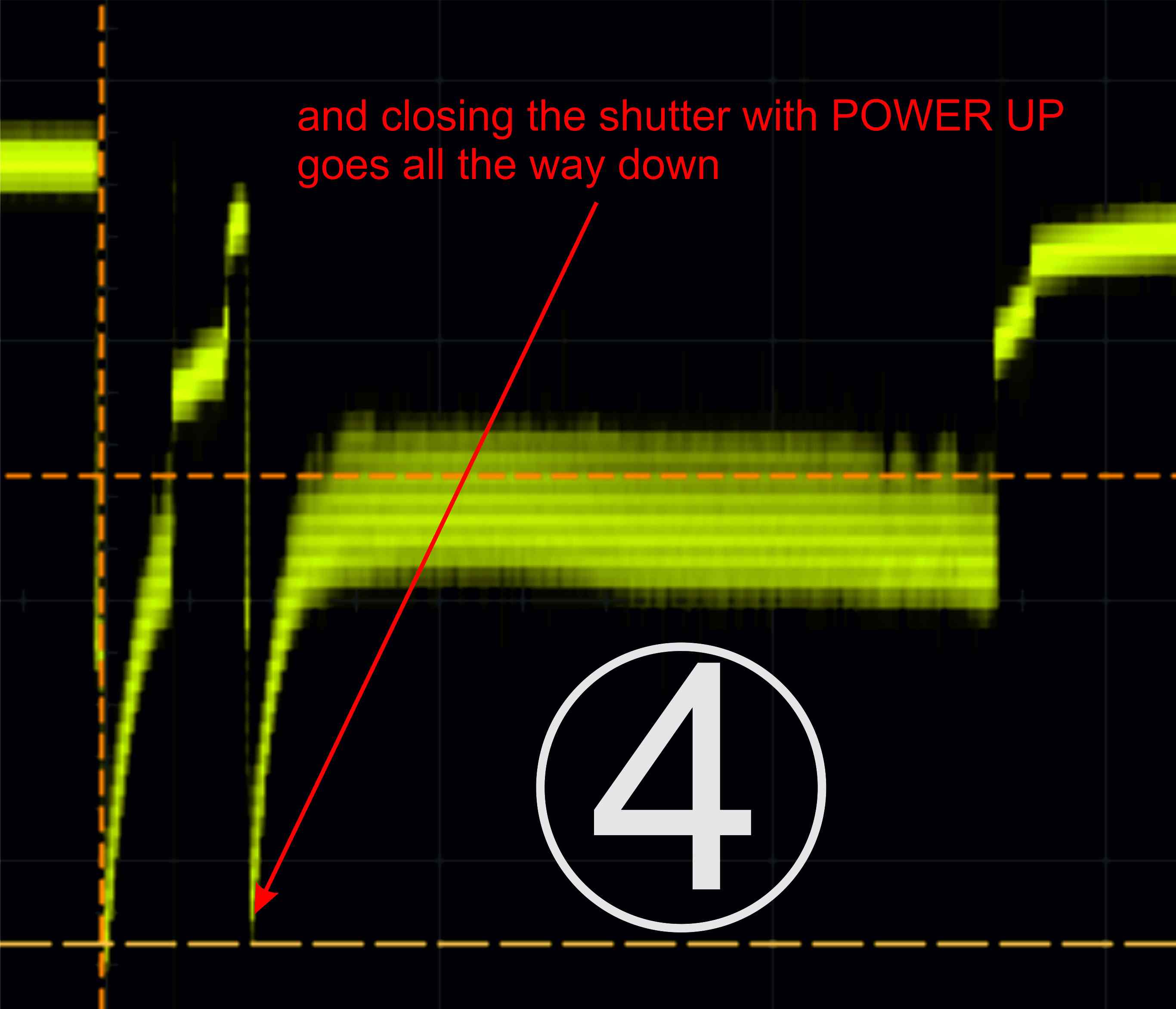 (4) We see the sharp drop of the POWER-UP operation, closing the shutter by giving full power to the solenoid!
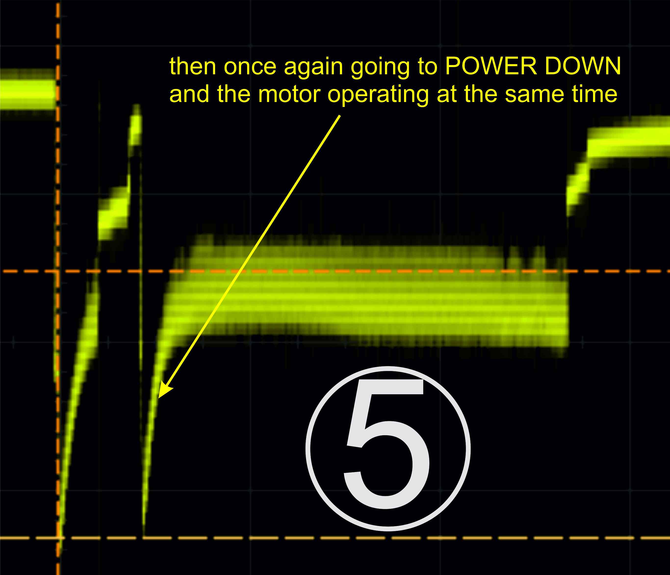 (5) And then again we go to power-down-saving mode, while starting the motor.
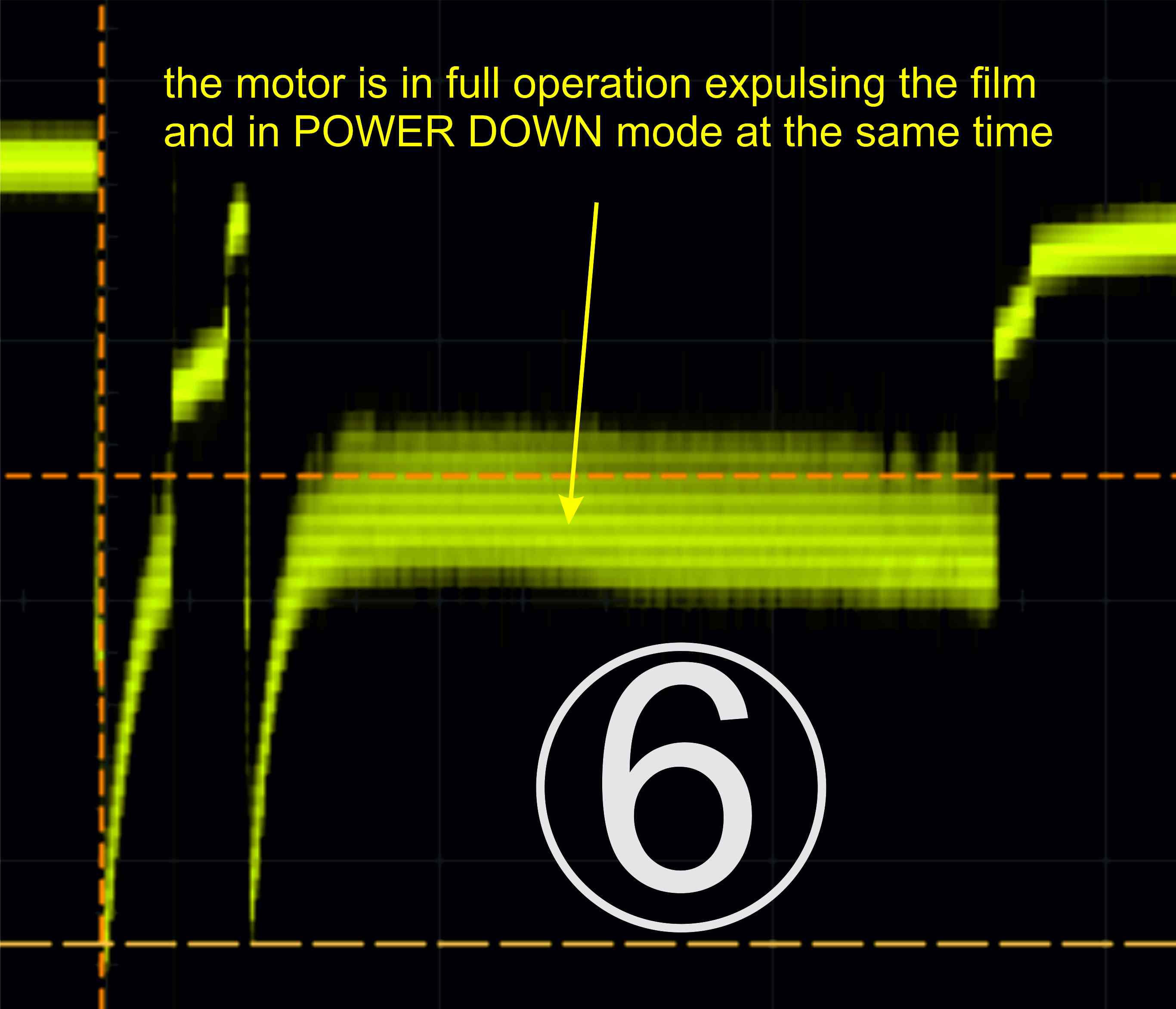 (6) Here is long burst of motor operation while expulsing the photo. Remember it is also holding the shutter closed!
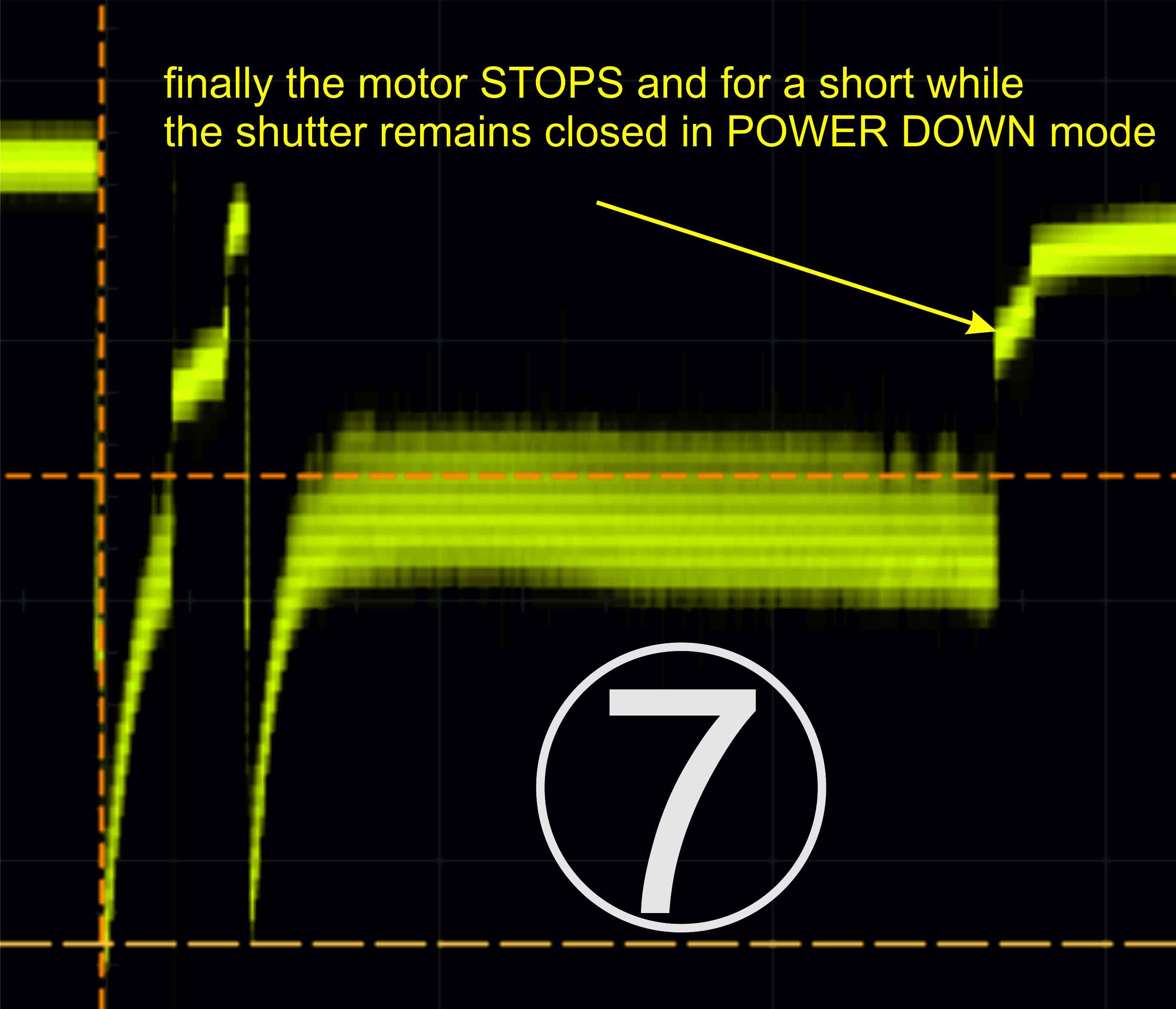 (7) When the motor stops we can only see the shutter holding close in POWER-DOWN mode.
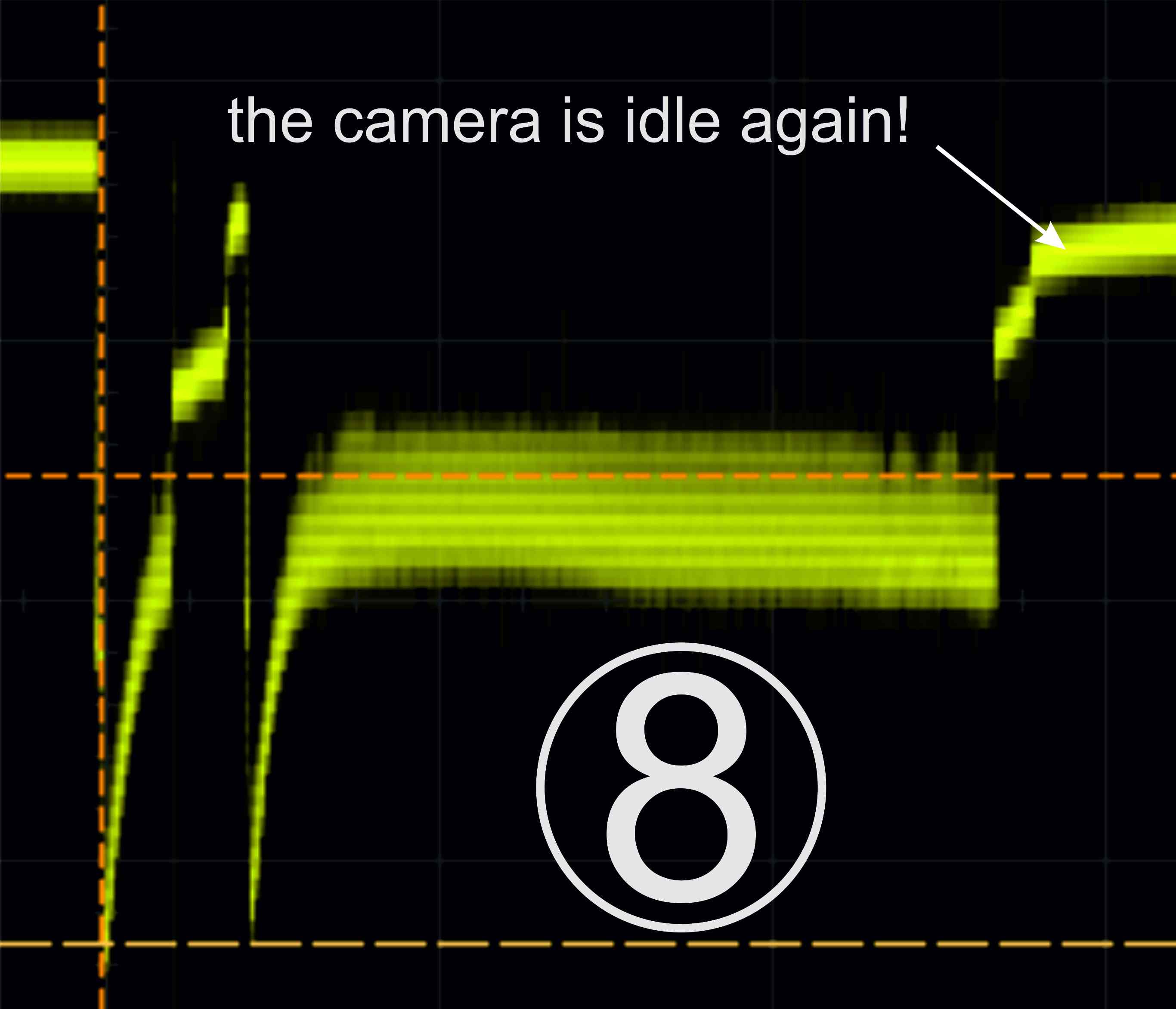 (8) And we are done! Back to idle.
So let’s recap, we have so to speak for levels of power drain:
-
when idle this is the least power drain.
-
the next is power-down mode.
-
motor operation
-and finally the highest drain is in power-up mode.
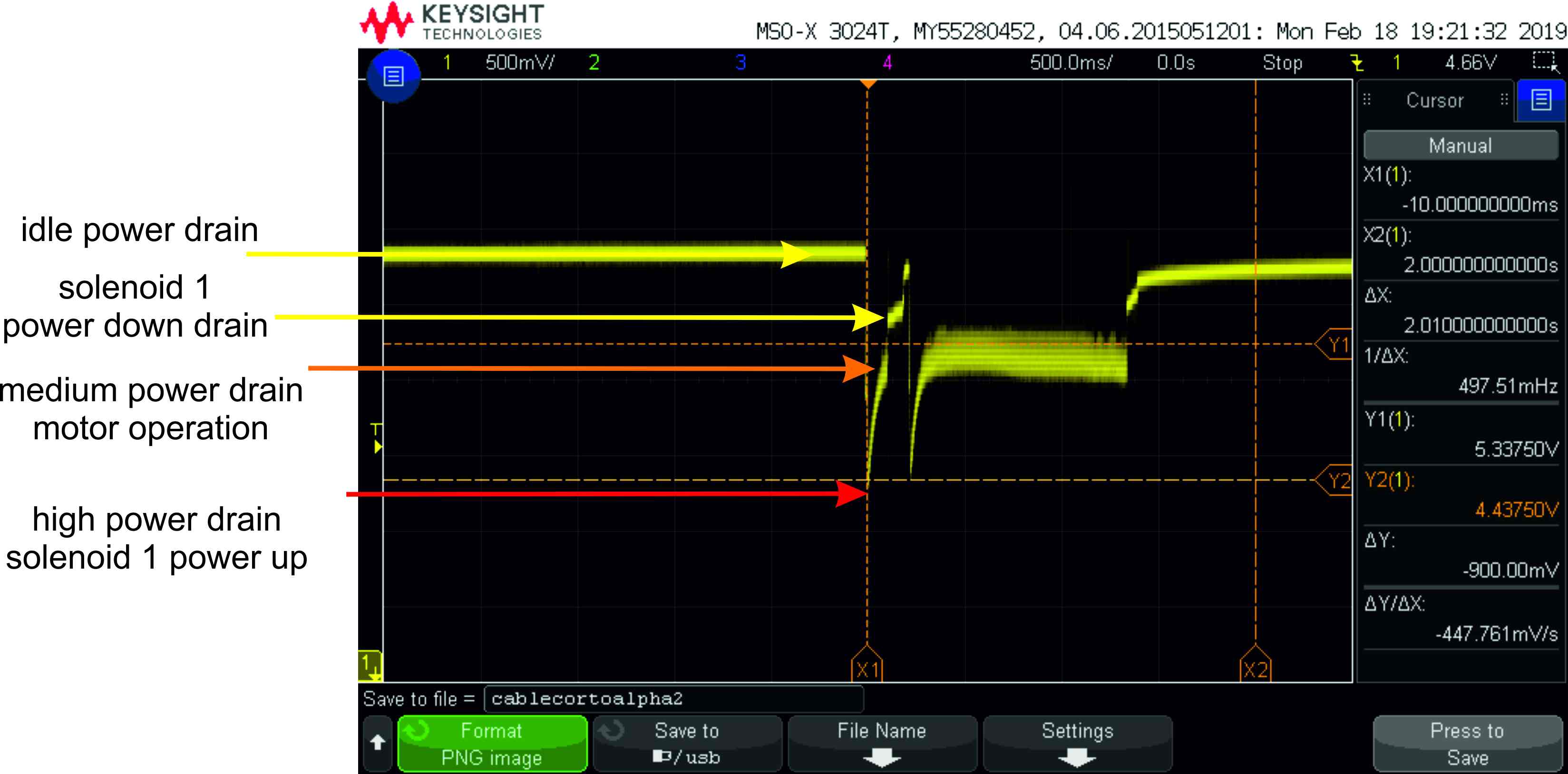
So answering our initial question, the voltage only goes down to 4.44V, so if we run the arduino at 3.3V we are supposed to be ok. We will see. Keep you posted. Please post any comments that you have!.
Comments