The SONAR flashflex header
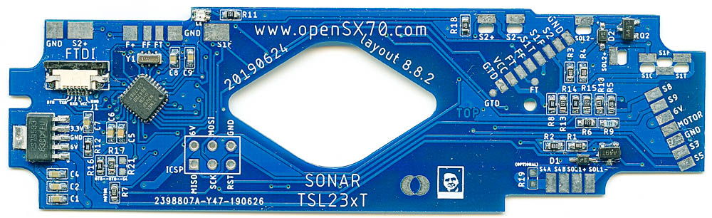
Today I have been able to assemble one of the new SONAR pcbs and have been able to program it through the ICSP. The most difficult part is soldering the QFN 32-pin Atmega328P microntroller. I always believed that was almost impossible, but it turns out it’s not that hard. I used the technique otlined in this video which is basically reflowing the chip with air.
Since SONAR is my “universal” PCB you can choose basically among three different hardware configurations depending on the parts, the, so to speak, normal, alpha version, the pre-alpha S4 version (explanation in part three) and the SONAR passthrough version. I did the later that is compatible with the normal alpha.
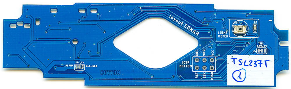
I have tested what I can test outside the camera, that is blink, and yes the LEDs blink, of course I can also program it, and in fact the new location of the flat cable is not that bad. And I have also tested that the TSL237T light-to-frequency sensor works. It all checks out.
Now I have to decide if I just build a “normal” alpha or go straight into trying to build a SONAR. If you are interested in the sonar operation itself I have included a very interesting explanation from the repair manual. Go to the bottom of the page for that.
But this post is mainly to explain what is the flashflex header, what and why it is there, and also clarify what I mean by passthrough.
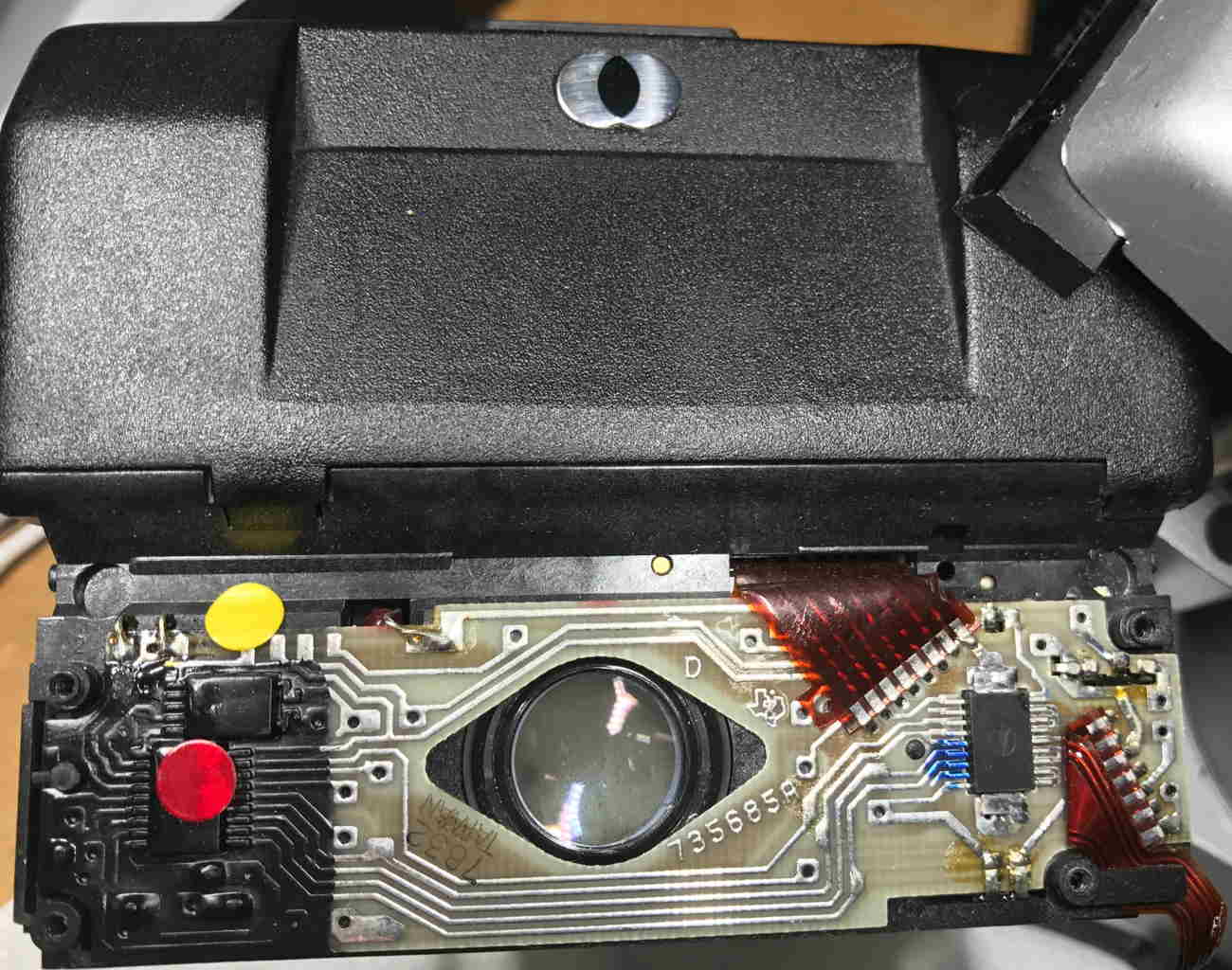
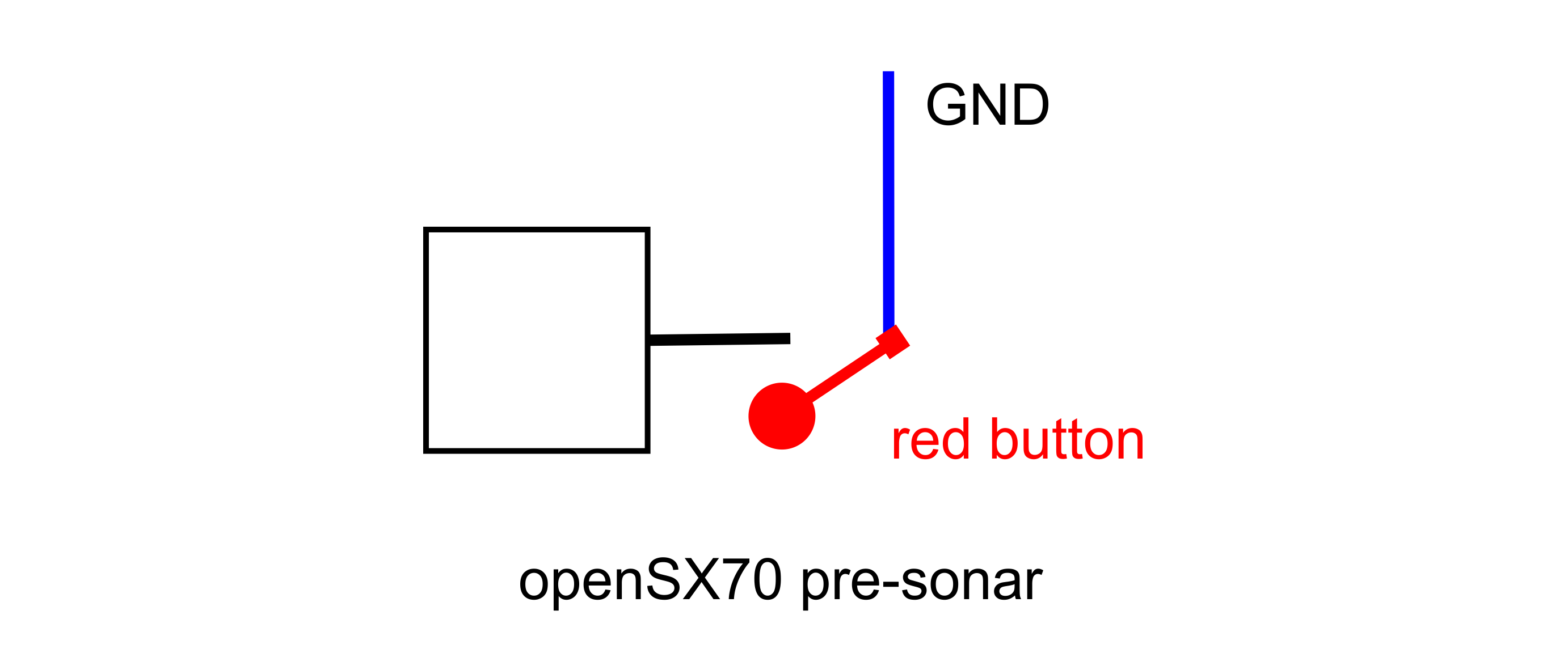
But before that, I want to talk about S1, also known as the red button.
The original SX70 S1 switch works like this:
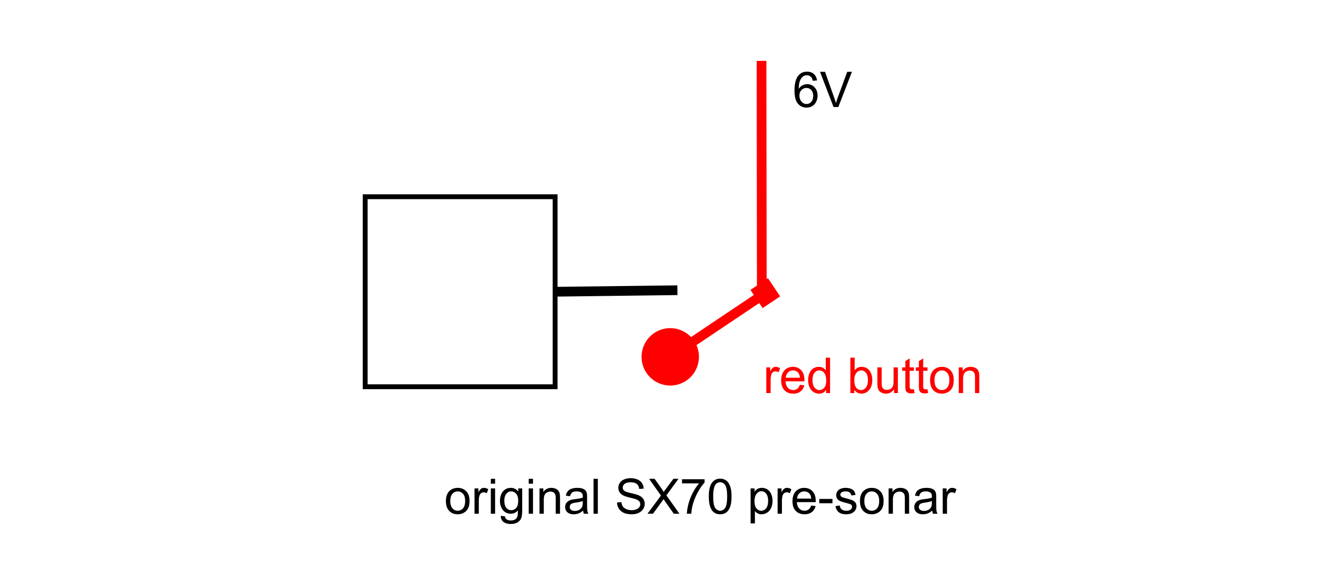
There’s the camera 6V, and when you press the red button, those 6V go to the ASIC, or, better said, to the brain of the camera. That way the brain knows that you want to take a picture and proceeds.
But as you should know, my arduino board works at 3.3V, so if I wanted to do something similar I had to turn that voltage down from 6V to 3.3V, that can quite easily be accomplished by means of a voltage divider. But I thought I could simplify a lot if instead of connecting the microntroller to 3.3V or 6V or whatever I connected it to GND. So that is what I did. I used an internal pullup resistor on the atmega and it worked perfectly.
But now I had a problem. Flashflex, the connector that basically goes “up” to the sonar assembly is a repeat (mostly) of other pads on the PCB, mostly it is Flash and S2 (S2 is also replicated on the left of the PCB, that is why I moved down the flat cable connector). Also the location of the FFA (flash firing assembly) is in the way of the SONAR (the original) low light LED. Of course the sonar also needs 6V and GND.

But as you can see in the graphic, there is also the S1 switch, that is back with a vengance: now there’s two, as you all know, the sonar has pre-focus, and picture-taking, esseantially two switches. And those also go “up”, that is the way the camera knows how to focus.
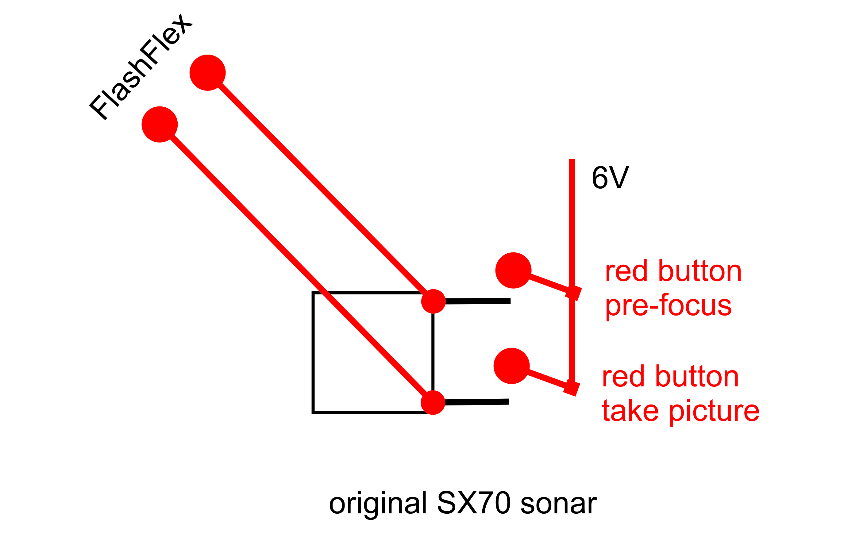
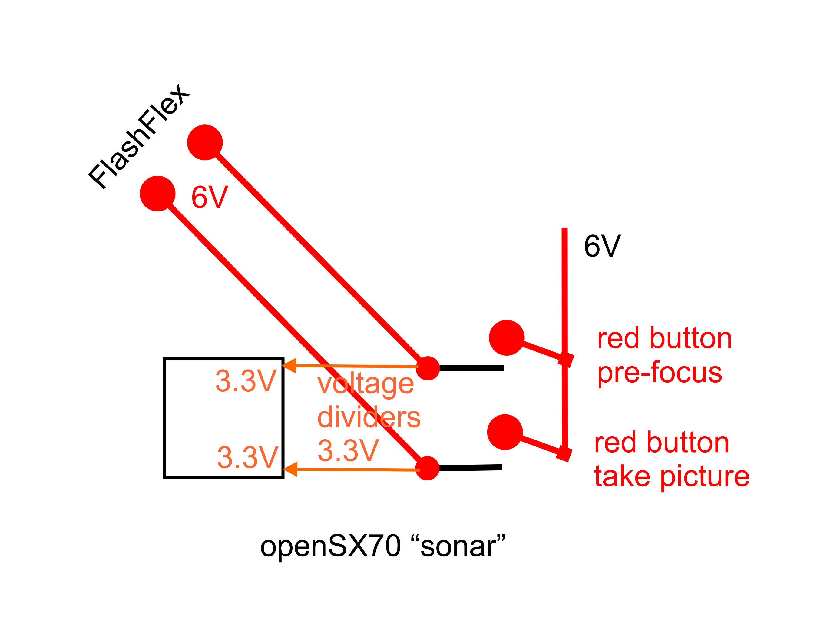
So now we have a common pin, lets call it S1C and then S1F (focus) and S1T (taking). But the thing is, if I want the camera to focus, I need to send those signal at 6V “up” no cheating with GND.
My PCB then, had to work at 6V, and add a switch. The solution is simple: again a voltage divider, so, when you press the button (focus, or all the way to “take”) I need to send those 6V to the focusing mechanism, BUT if I want to know that either button has been pressed I need a voltage divider to connect at 3.3V (each) to the Atmega. Of course, in the software, I have to “inverse” the logic of the S1 operation, and add another button…
So why do I call it passthrough?
I feel that maybe something more advanced can be accomplished, maybe I can pre-focus via software in the future. At the moment I hope the camera will work (in the SONAR part) as an original or close.
But wait, there is another pad named GTD. What is that for????
I think it is the way the sonar assembly told the camera that focusing was accomplished and to proceed with whatever… I think (this is only my conjecture) that it stands for Gone The Distance. I was hoping I could some distance information out of the signal, but I fear it is just a heads up signal to the brain. In my case it is voltage divided to 3.3V (from 6V) and connected to the microntroller.
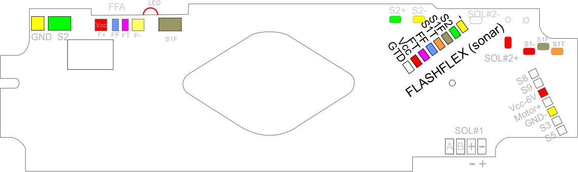
So here you have the colour-coded map of the pads on the original PCB that are translated to my own.
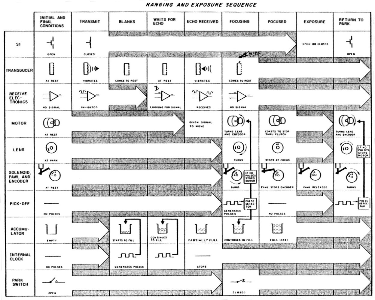
EVENTS SUMMARY (from the repair manual)
The following chart graphically portrays the sequence of events. Basically, the chart shows how the various steps in automatic ranging relate to each other. The following written description explains this interrelationship.
When the S1 button is pressed, the transducer transmits a pulse of ultrasonic waves (chirp). This chirp reflects from the subject back to the transducer, which receives the retuming signal. The automatic ranging system measures the time between pulse transmission and reception of the reflected pulse. This time is proportional to the distance of the subject from the camera. The lens is now turned automatically to this distance and locked into position. After the lens has focused, the exposure is made.
Before an exposure, the lens is at a fixed position slightly beyond infinity, known as “park”. At the time the ultrasonic pulse is transmitted, an electronic counter is fed by electronic pulses until the reflected signal is received at the transducer. When the reflected signal is received, amotor is turned on which drives the lens and another special gear known as the “encoder”. The encoder has a circle of holes near the edge. Positioned over the edge of the encoder is a horseshoe-shaped piece of circuitry known as a “pick-off assembly”. As the encoder moves round, driven by the motor, the pick-off assembly shines light through the holes from one side of the encoder, and detects the light by a photocell on the other side of the encoder. An electronic pulse is generated each time light is detected through one of the holes passing by the pick-off assembly.
The electronic counter, which had counted the pulses generated between the transmitting of the ultrasonic pulse and the receiving of the reflected ultrasonic pulse, now counts the pulses generated by the pick-off assembly and the encoder. The counter stops counting when it has received a fixed number of pulses (128). When the counter reaches this number, a solenoid is actuated, moving a pawl into a ratchet tooth stopping the movement of the encoder and the lens immediately. The lens is now focused at the correct position. The motor drive signal is removed at this time, and the motor coasts to a stop through clutch action while the pawl holds the lens in position. Once the motor stops, the camera continues to run through its usual exposure cycle.
Then, the motor reverses direction and drives the encoder and the lens back to the park position. This finishes the cycle. lf the subject to be photographed is 3 feet away, the number of electronic pulses fed to the counter before the rellected signal is received is 93. To reach a total of 128, the encoder gear must move so that 35 holes pass by the pick-off assembly. This rotation corresponds to a lens rotation bringing it to 3 feet.
If the subject is so far away that the reflected signal takes a long time to return to the transducer, or never returns, the number of electronic pulses fed to the counter is 124. The encoder gear then moves so that 4 holes pass by the pick-off assembly. This moves the lens from “park” to a position known as “synthetic infinity” or the “hyperfocal distance”.
A safety feature is designed into the ranging electronics, in case jamming occurs while the encoder gear and lens are being driven (either when focusing or when returning to “park”). The pulses generated by the pick-off assembly and encoder must be fed to the accumulator at a rate higher than some critically designed speed, in order for them to be counted. If the accumulator has not reached its full count of l28 pulses before a time period known as the “jam time”, the motor drive signal is removed. When being driven back to “park”, the pick-off assembly is generating pulses, which if not generated quickly enough, will again shut down the motor.
Comments