Why no model 2? the "S4" switch (UPDATED )
I want to speak a bit about one of the differences (from the electronics point of view) between earlier SX70s and later “ALPHA” cameras. That is the S4 switch: you can find it in earlier cameras, but not in the later ones.
My disclaimer is that I don’t have much experience with the cameras and their technical differences, but this is an obvious change. I recommend reading the article “The race for the SX-70” written by Tekla S. Perry on the May 1989 IEEE SPECTRUM magazine. It is very interesting.
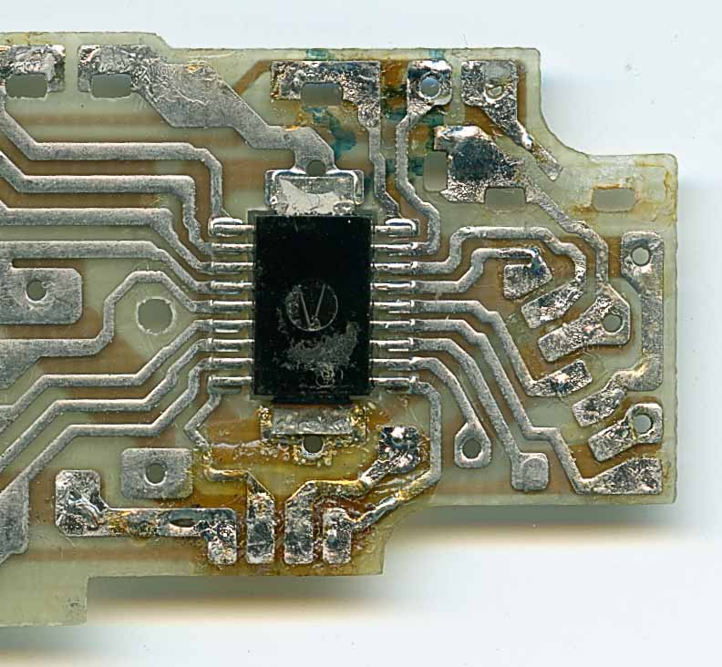
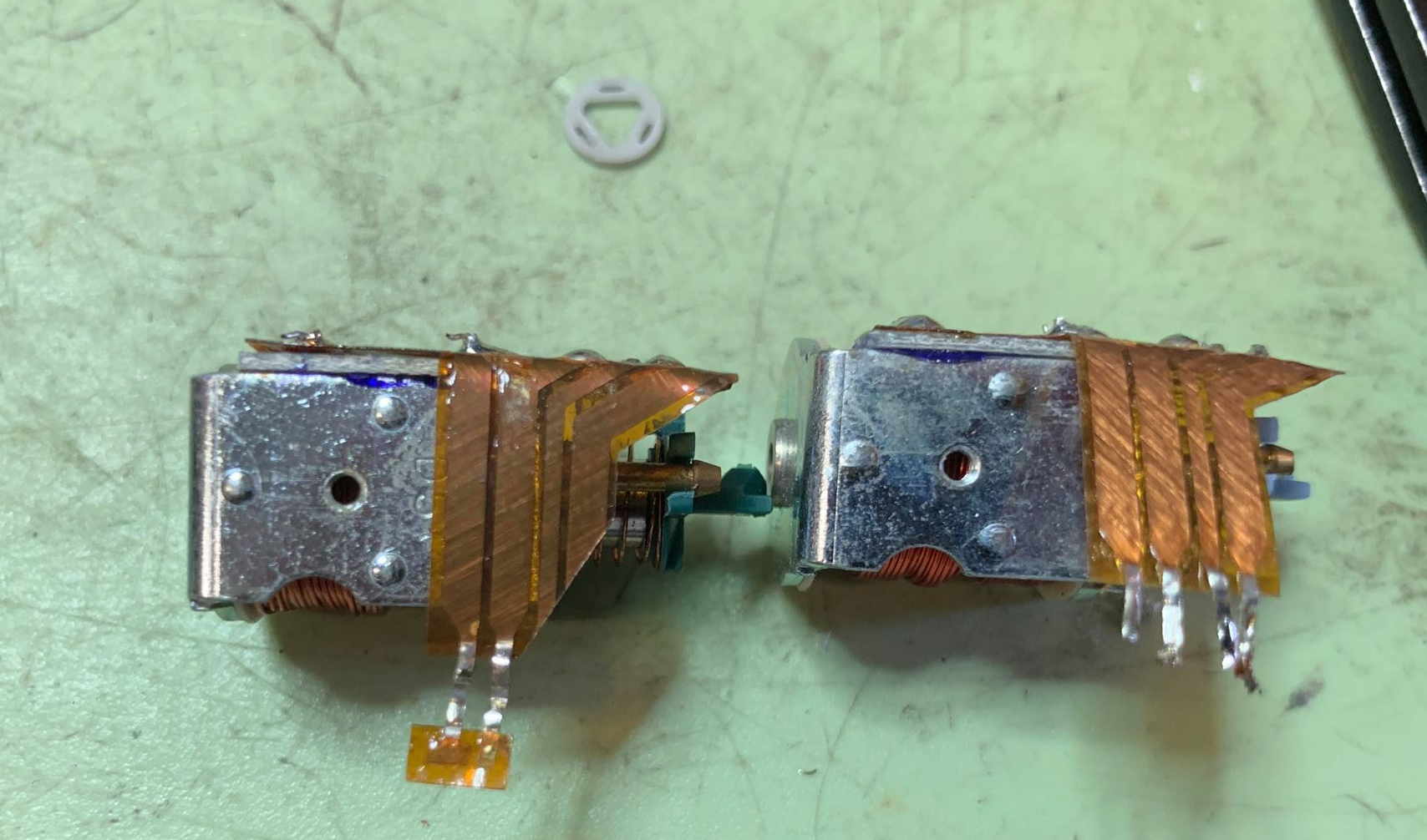
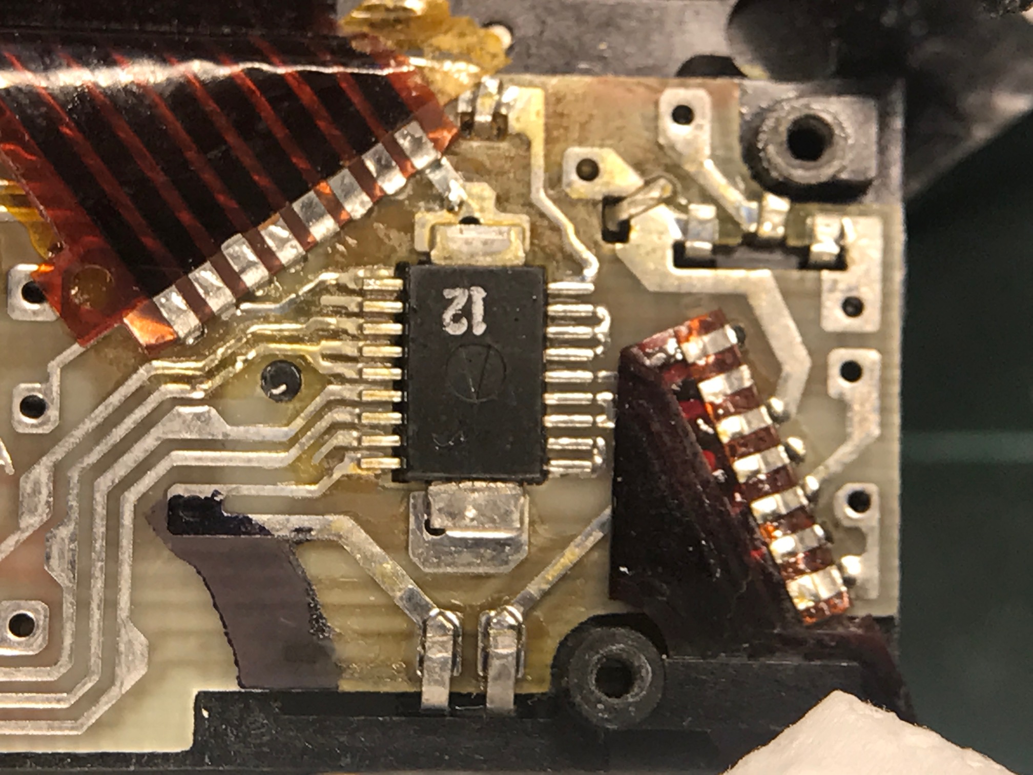
So the difference is quite aparent: the solenoid 1 that operates the shutter has four connections on earlier cameras but only two in later ones.
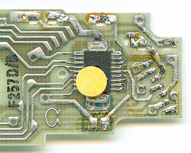
You can see in this detail picture only two connections and in the previous one four.
So let me try to explain the differences:
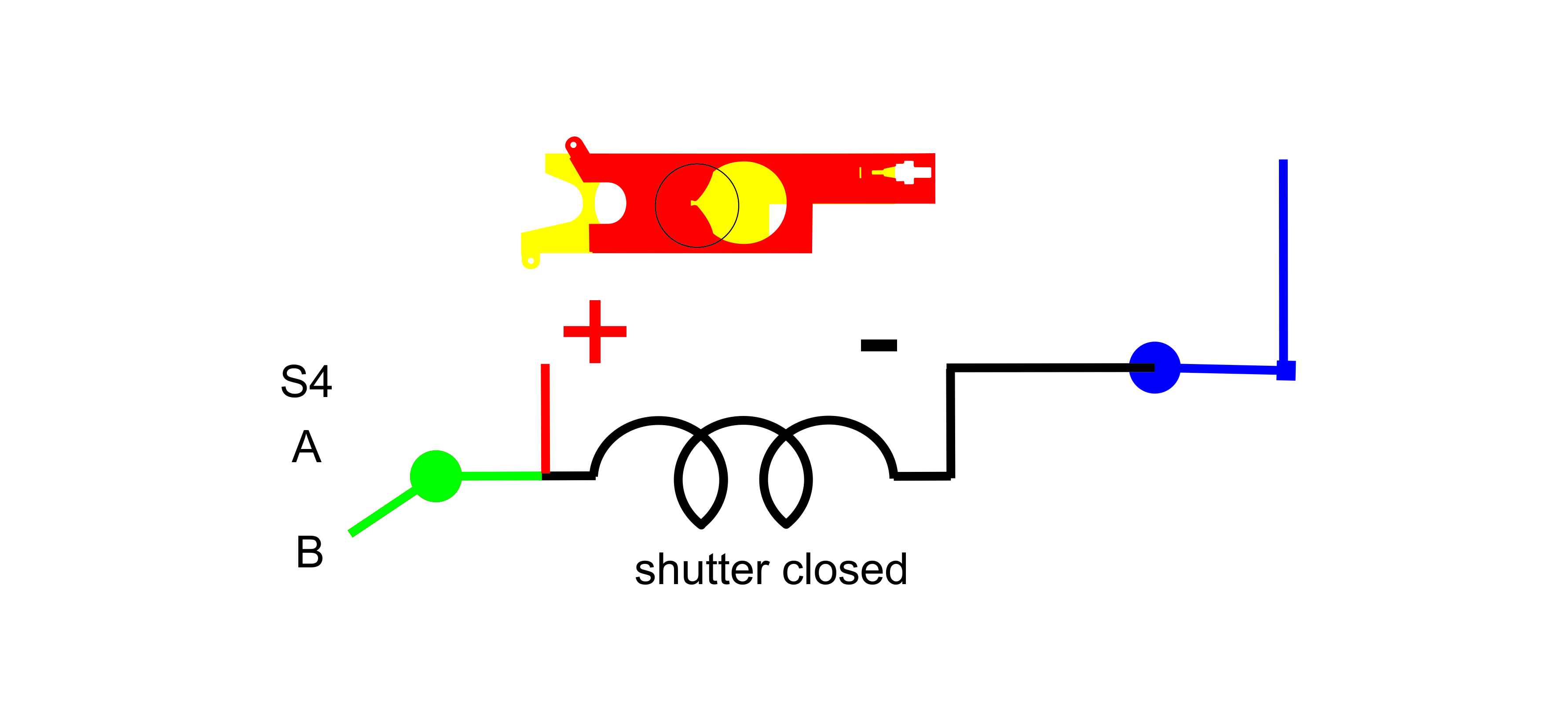
Original cameras had the S4 connection: Think of the solenoid as a magnet that moves a plunger, that is mechanically connected to the shutter/aperture blades: when powered up the shutter is closed, and when there is no power the shutter is open (most of the time)
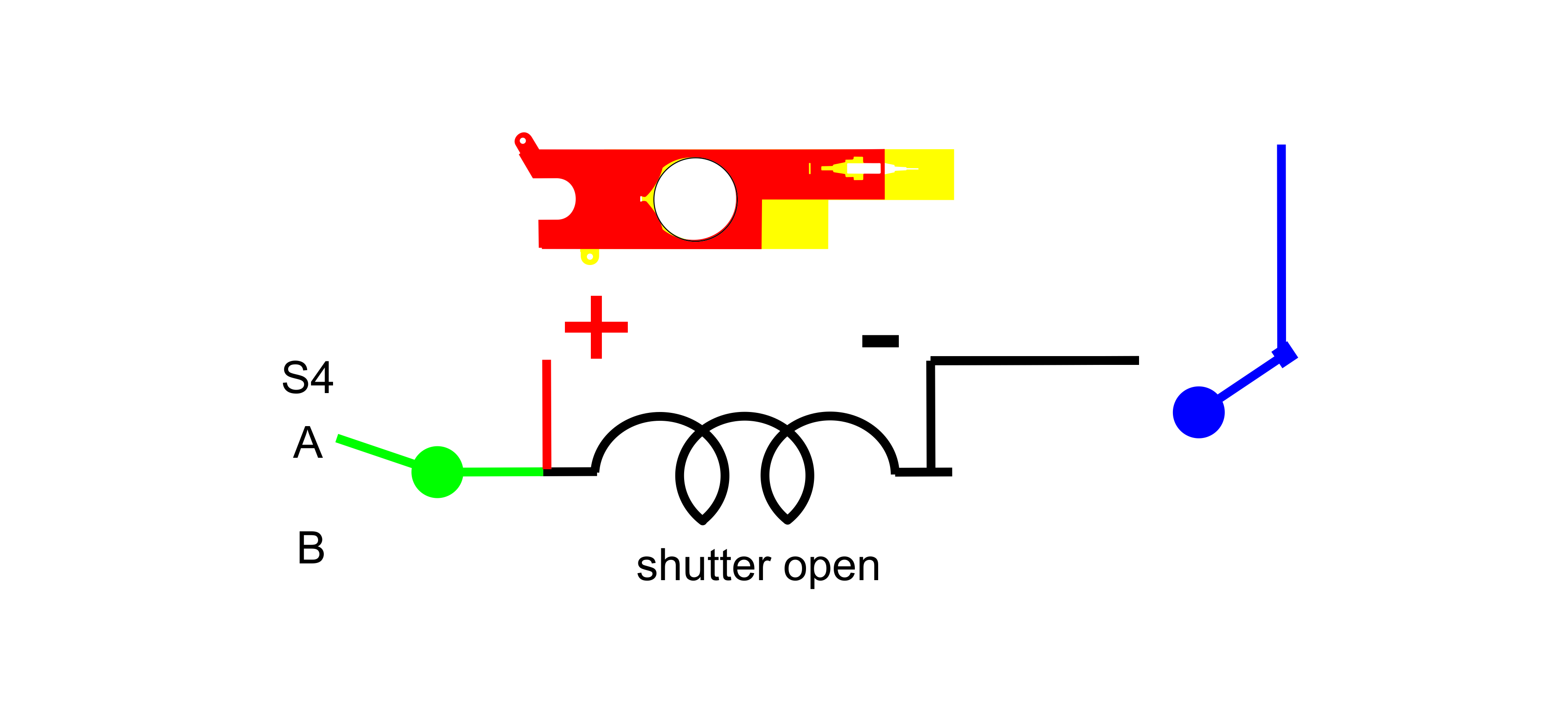
So just put 6V during the right amount of time and… ZAP you got a picture.
But as you can see, there’s more, there’s A and B. This is a mechanical switch, basically a relay. So when the solenoid is idle, the + is connected to A BUT when the solenoid is engaged, then + is no longer connected to A but to B. In the repair manual it is referred as CA and CB, probably meaning Closed A position or Closed B position.
First thing that comes to my mind is that this is totally innecessary, but not only that, friction, most certainly makes closing (specially) the shutter, much slower than if none of that would be there.
So my question is WHY? why would they do this mechanical expensive and performance-afecting complication???
In my mind the answer is clear. We know for a fact from the Repair Manual, that the solenoid draws too much power and that was a huge problem for the companies developing the ECMs (PCBs in modern lingo).
They needed all the power they had to start moving the blades and everything, but, the knew that once there, they could go into a sort of “power saving mode”, and thus have all the resources to move the motor and all the mechanics.
It is my contention here, that those original S4A-S4B PCBs used that switch to mechanically engage the aforementioned “power saving mode”
So please bear with me, that this is not rocket science, if we feed the +6V voltage to S4A, the solenoid will move to the engage position, and then we can feed the “power saving mode” version of the 6V (maybe a resistor to limit current or voltage)
Here we can see the mechanism.
So what happens when the “ALPHA” ECMs come along. I think that the T.I. engineers devised an electronic way to limit current and do the “Power Saving Mode” electronically, and thus the complicated mechanical contacts were no longer required.
I can only assume that the new solenoids where substatially cheaper to manufacture.
Here we can see the “newer” version of the solenoid, very simplified.
But of course, we still have to go to “Power saving mode”. I don’t really know how they acomplished that, maybe with some sort of delay, maybe the checked the photodiode to know when the camera had the shutter open.
I myself in the openSX70 project use a technique known as PWM pulse witdh modulation. It is basically turning on and of the solenoid at a certain frequency. It it were a lamp or an LED the efect is that it would be dimmed.
This is a sniped of code:
void shutterCLOSE()
{
  HighSpeedPWM ();
  analogWrite(Solenoid1, 255);

  delay (PowerDownDelay);                                        //Wait for the SOL#1 in BC position, more tests perhaps need changed to 25
  analogWrite (Solenoid1, PowerDown);

  return;
  //return;
}
So this a funcion, you can call it a command, to close the shutter, so I issue it whenever I want to close the shutter. It is called shutterClose. All the instructions within the function are inside the curly parenthesis.
HighSpeedPWM is just another command. This is to set the characteristics of the PWM. I found early, that at certain frequencys the solenoid resonated, making a noise.
Now the main command: analogWrite this command send the instruction to engage the port, so I say engage “Solenoid1” (that elesewhere is defined as a port, in this case is D3 ) and the “power” I want to use (as a number 0-255), I can use 0 (nothing) to 255 (maximun), so I do maximum, remember, we have to “move” the thing all the way to the closed possition. So once I assume I am there (I wait the PowerDownDelay amount of ms defined elsewhere) I engage the “Power Saving Mode”
To “keep” the shutter down I define PowerDown with a value, lower than 255, it can be 155, it’s usually trial and error. It has be high enough to keep the shutter open) I have found that, for instance Pieter Meloen, had trouble with this, and had to go to higher values. As always, you can fine-tune everything.
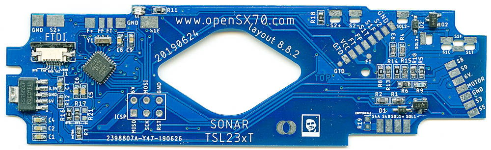
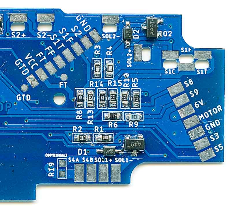
I have added in the bottom of the PCB a way to select the type of operation for Solenoid1, it is a jumper named, apropriately SEL_S4: if the center pin is connected to the one of left (default) it assumes an ALPHA camera, if the center pin is connected to the pad on the right my new “system” for S4CA and S4CB.
Here’s that part of the schematic:
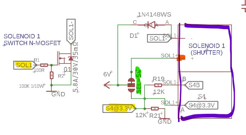
Highlighted in yellow are the Micro controller (Atmega328P) pins “SOL1” as an output pin of the Atmega driving the solenoid through a voltage divider (Solenoid1 operates at 6V, but the Atmega works at 3.3V), and “S4@3.3V” is the pin that is notified when the switch is engaged (in the pre-ALPHA type of Solenoid).
As previously note I have modify SEL-S4 (highlighted green) jumper (per default 6V us connected to the SOL1+ pin on the Solenoid, highlighted orange).
So when you modify the jumper no power goes directly to SOL1+ and in resting position it goes to S4A, all 6V. But when the solenoid is engaged instead it goes to S4B through R19 (disregard the values, I have not tested or thought the values) So we can use R19 for “power saving mode”.
And THEN the combination of R19 and R21 is a voltage divider, that, connected to a Micro controller input (S4@3.3V) signals exactly when the solenoid is engaged…
So R19 is by itself making the solenoid go to “Power Save Mode” electronically, thus all that PWM can be removed. An R19 in combination with R21 is a voltage divider to bring 3.3V to the Atmega when the Solenoid is engaged.
Sometimes is difficult to determine the generation of a camera as it might have been fixed in its time. I got the following picture from a person that knows way much much more than I do, you can see how a full S4 solenoid is “repurposed” for use in newer cameras. In fact it is known for Polaroid to have recalled early cameras, for instance with the fresnel replacement mirror with the focus aid…
Now many conclusions and questions: it is quite clear that these became quickly obsolete, I still argue that makes the shutter slower (and it is already SLOW) and thus that all new designs have only the 6V+ and GND (negative) pins.
One would also argue that there no need to use S4A/S4B at all, you just can perfectly do without. It is simpler, more standard, and arguably elegant.
And your question might be, why do you support S4CA/S4CB in your SONAR (experimental) PCB when by that time original SONAR PCBS had long forgotten S4CA/S4CB?????
Glad you asked: First because one of the design goals of the PCB was being (as much as possible) “universal” I try to shape the PCB in a way that fits most cameras and with connections where other cameras have them for different reasons.
Here’s my point of view. First and foremost, it is there, has a purpose: then I want to use it: I want to do it right! So SONAR is not only an attempt to support sonar cameras (remember the first manual and auto SONAR SX70 was an openSX70 camera!) but also early solenoid 1 configurations as discussed here.
But I also think I can improve in a sense making use of what I got: I can definitely use it for the “Power Saving Mode” by using a resistor, BUT, with another resistor I can do a voltage divider and connect it to the microcontroller. THis way I know certainly when it is open, and it might yield to more exact timings specially in the faster shutter speeds (let’s say faster than 1/30th).
So when they ask me if the openSX70 mod is compatible with previous models non-alphas I tend to say “NO” but in a sense its not totally true:
-auto exposures via integration and the magic number, probably are not afected and work well. One might assume the same back in the day.
-it will make manual speeds slower. (one can assume that this by faking the manual fast shutter speeds, thus making them in fact auto via integration). Of course I would never to that, but again, fast speeds are a challenge.
I hope to make my first Model2 using a SONAR PCB with TCS3200 camera to test all this ideas.
And to be sincere, I hope I can find replacement springs for the solenoid in an attempt to make the shutter faster.
You can call me crazy, I am pretty sure I don’t know what I am talking about! Keep an eye in this post, as I plant to correct it and improve it in time.
Comments