The BodyFlex circuit
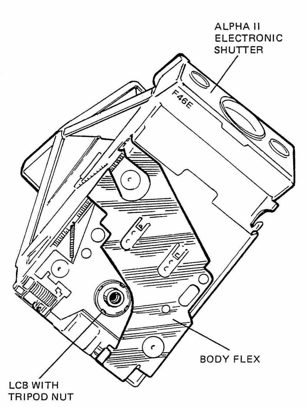
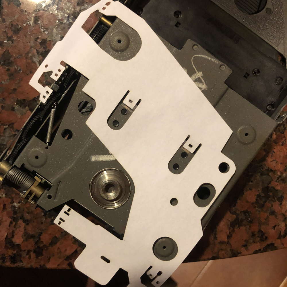
The bodyflex PCB
The bodyflex is the circuit that is on the body of the camera, connecting S3 S5 S6 S7 S8 and S9, also connects to the battery, and to the lensboard. It has one, or maybe two components: the driver that controls the motor, orogonallu a TO-5 round chip, called the MCC, and later the MCM, motor control module, a DIP-8 with five legs. Maybe, we can consider the motor also a component, but that’s it.
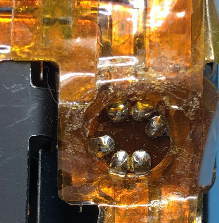
This summer I took apart an early model 1, these cameras have significan differences with later models, some are obvious and we all know them, like the lack of tripod mount, but others are internal. So I was removing the ancient PCB on the body of the camera and noticed that the MCC(motor controller circuit)was a TO-5 metal chip with a heatsink, much different from the 5-legged DIP-8 found in later models. But when I began to take it appart, the flexbody, dark brown, I think made of kapton, began disintegrating on me. It was ugly, and I wasn’t the only one, that is when I decided to “make a new one”.
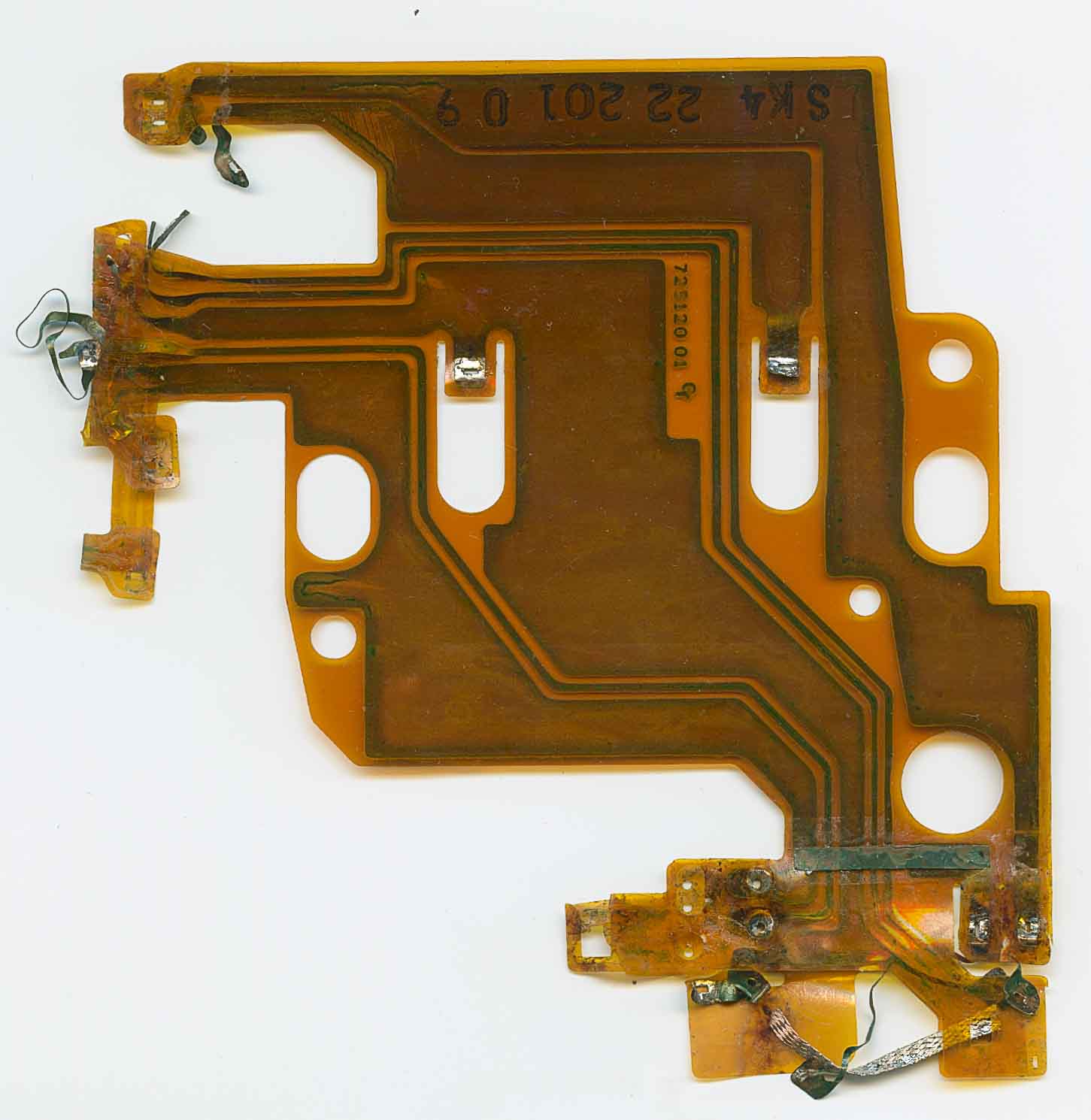
It is a sorry sight to see, with some solder wick stuck there like spoils of a battle. Not nice.
Ok, first a disclaimer, I am not an expert and this is not a tutorial, and I definitely have no idea of what I am doing.That being said I am going to try to explain how I want to it. And remember, as Naomi Wu says, if I can do it, you can do it, it’s just a matter of keep on trying.
So my plan is to scan the original at the highest res that I can, and try to trace from there.
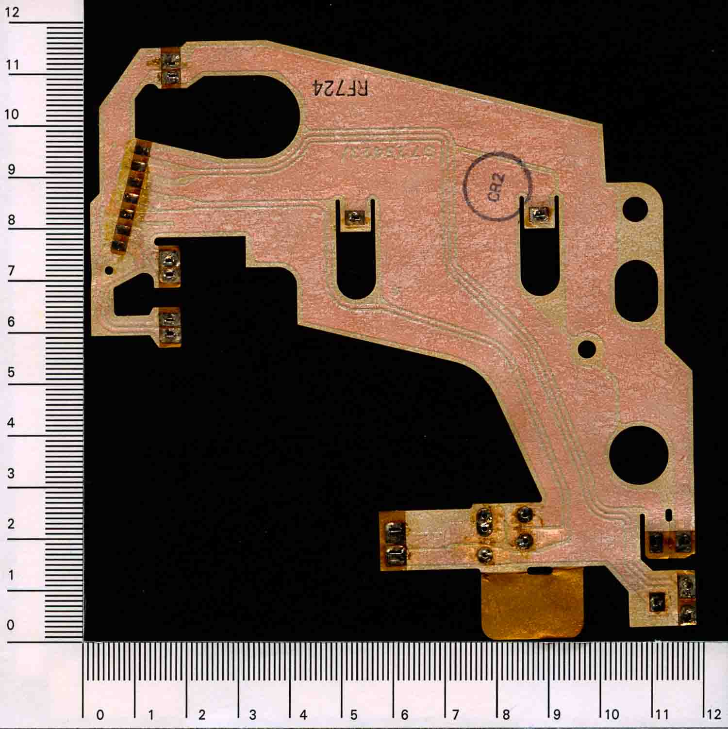
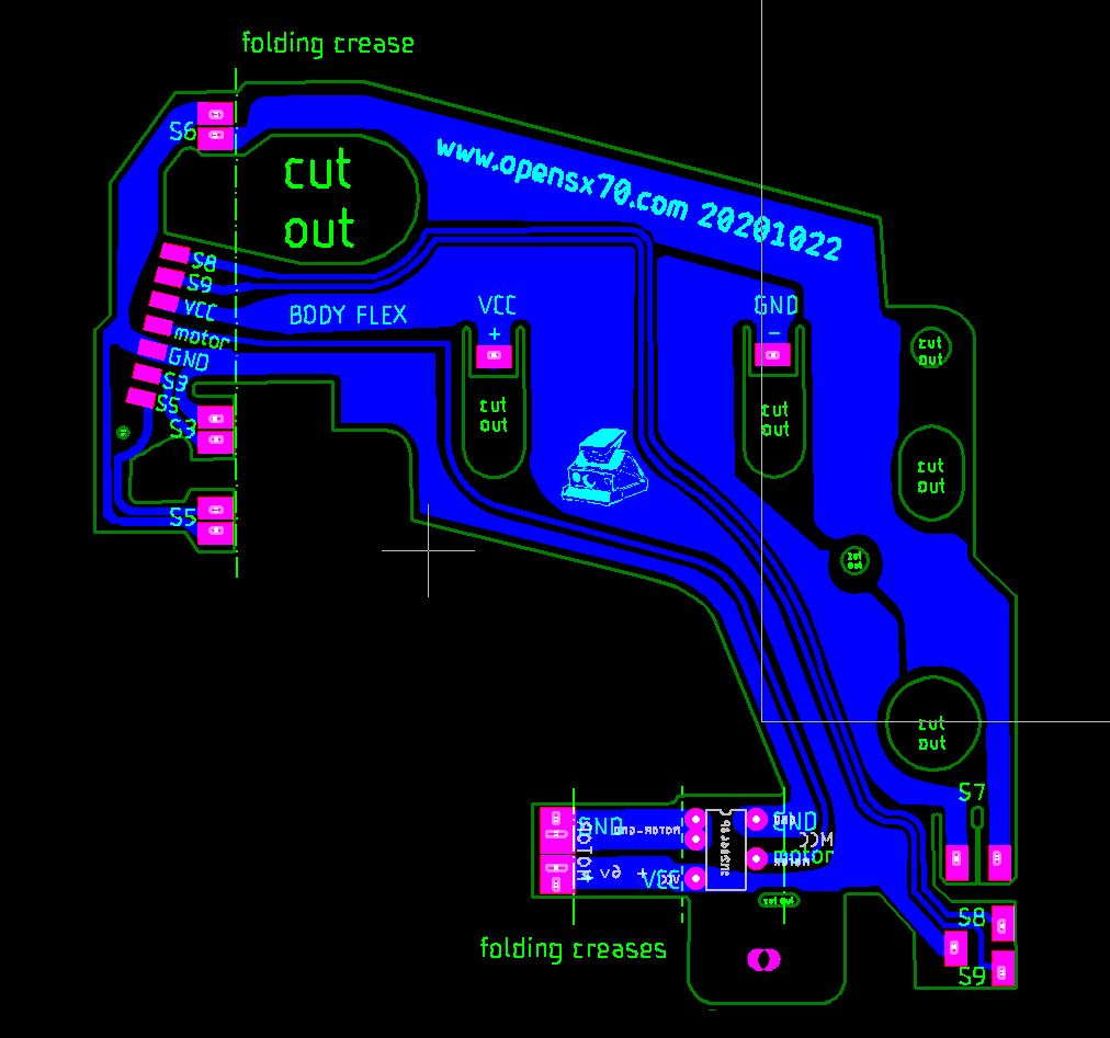
So from here I trace it in Corel, to have a vector file. From that I made a DXF that I imported into Eagle.
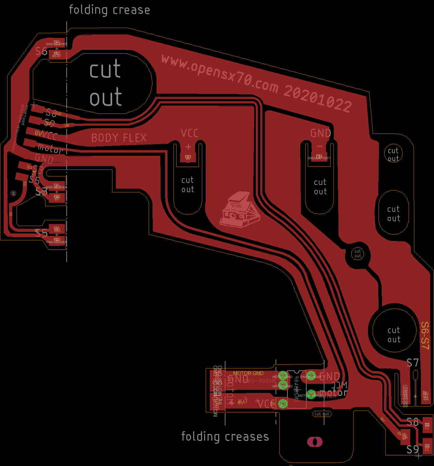
It’s not that I try to improve it, well, actually first I had it laser-cut on paper, so I could check the dimensions.
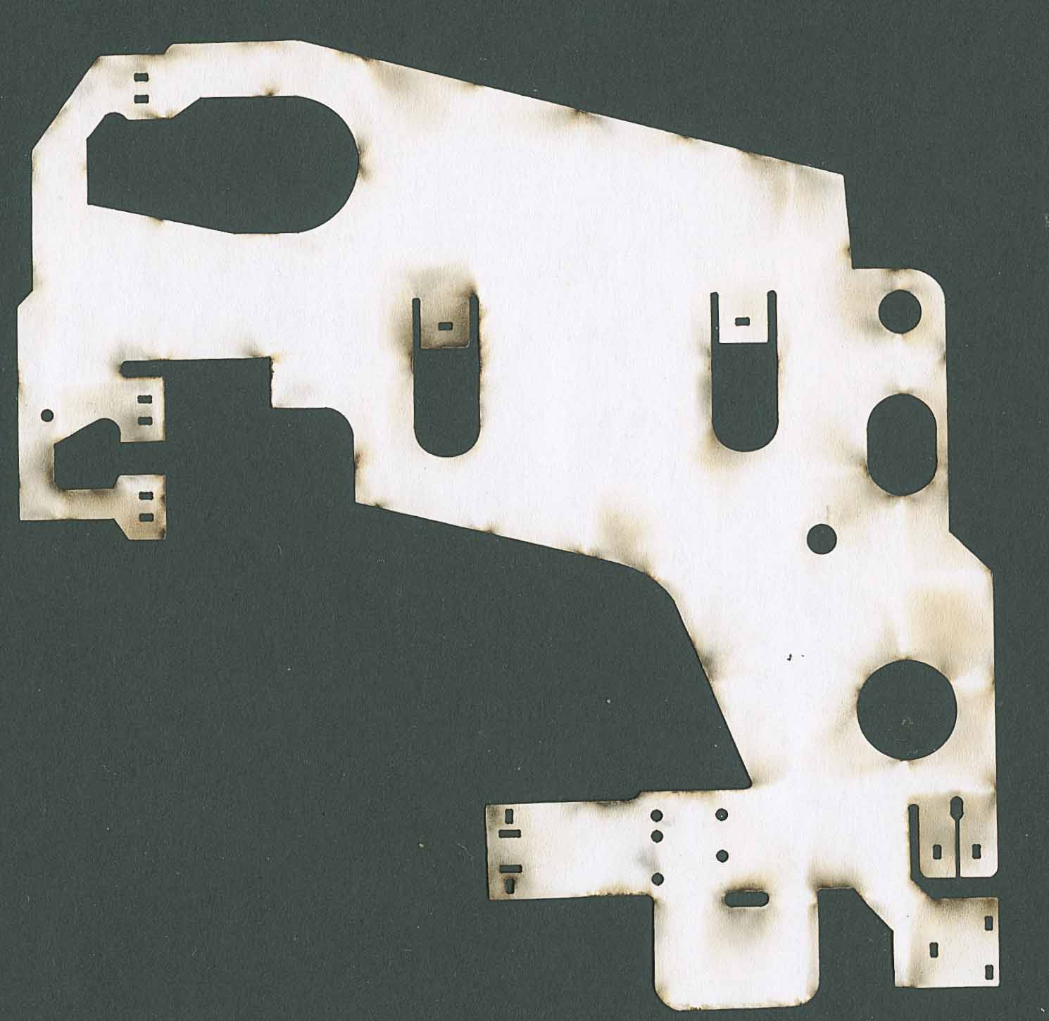
As you can see, that didn’t go too well, but it was enough to detect some minor adjustments needed.
There’s a few modifications, first I wanted to take into account the new Mabuchi motors, used by the repair shops, so I added extra connections to the motor.
Then I decided that it was going to be black, as in why not???
Of course I also added some of my logos and art, otherwise it wouldn’t be my board!
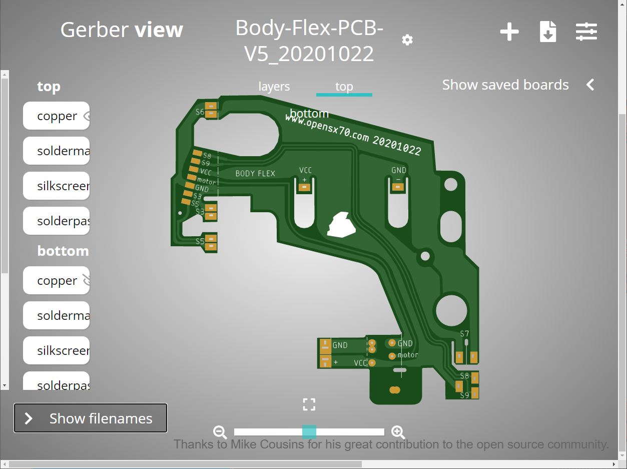
These are the images from the PCBWAY gerber viewer and the ViewMate viewer.
It is still a work in progress, since I want to take all the precautions as I have never ever made a flex pcb. Fortunately, it seems that with PCBWAY it’s as easy as making a regular PCB. Also they have been too kind as to subsidize in part this experiment of mine, so, once it goes to fabrication I will certanly share my experiences and results. I have looked in the internet and havent found much tutorials on the subject.
It is also reassuring that PCBWAY check the files you send for any errors, that might concern fabrication. That is awesome!!!
I also want to mention that I have bought the best SX70 repair manuals that I have seen. There are different options but I got the Polaroid SX-70 Service & Repair Manual: November 1973 w/ Bulletins & Updates
That is expensive at 69 bucks, but it packs soo much stuff, many diagrams are actually foldouts, the images and text is crisp.
I, myself, got a red 3-hole binder from the US, to make mine as original as possible. It’s amazing.
I also recommend Polaroid SX-70 Alpha Repair Manual Supplement to the SX-70: Reprint this one comes binded, but there is so much new information about ALPHA that for 18 dollars is totally worth it. I mean if you have to go to the copy shop to make a paper copy it would cost probably more.
I want to make clear that I have got absolutely no perk from the ebay store goodygifts, I even asked for a discount and didn’t get it!!
Just to ponder what we are talking about, and related to the question at hand, the bulletins are like letters to the repair shops. This include technical information, this is an example:
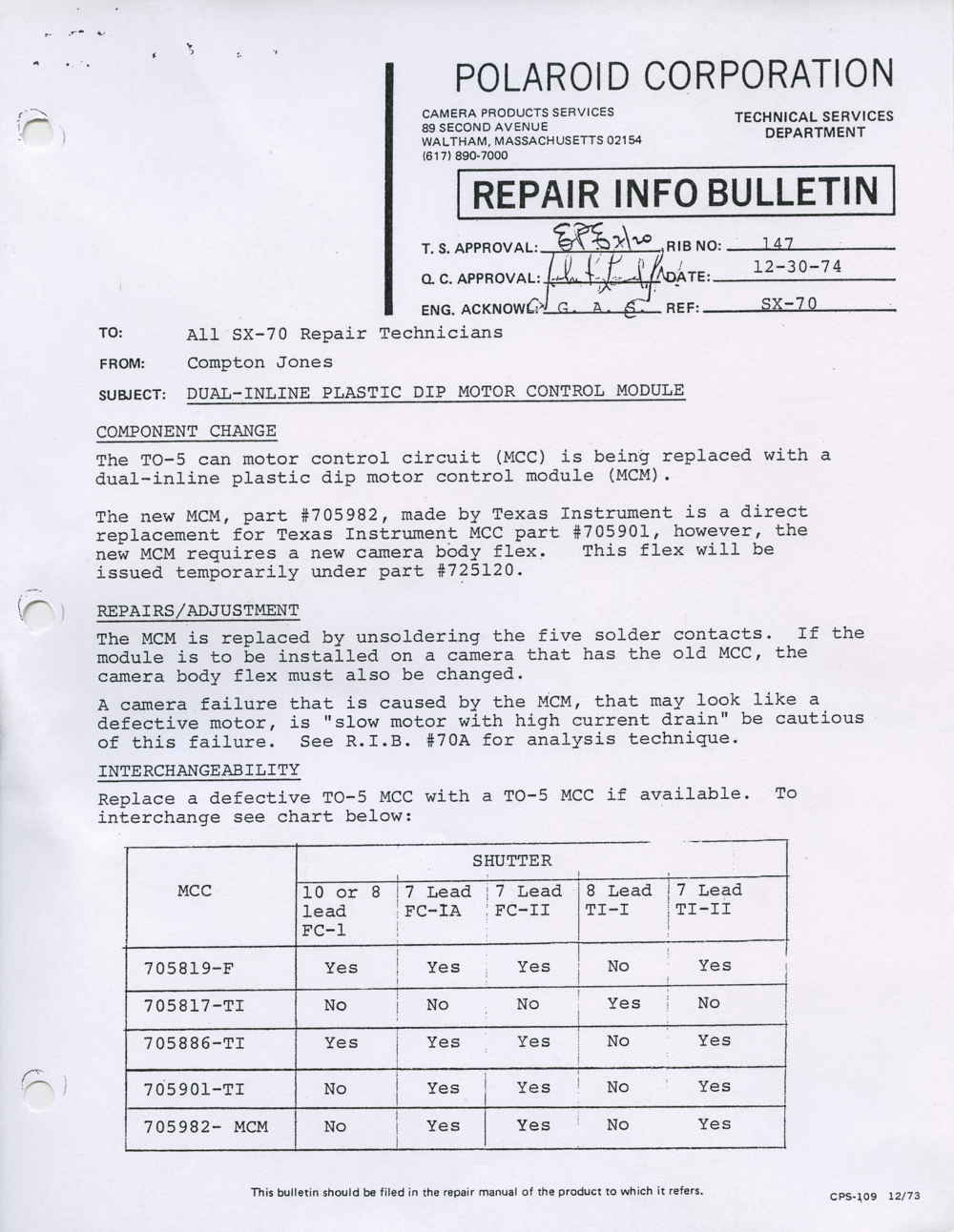
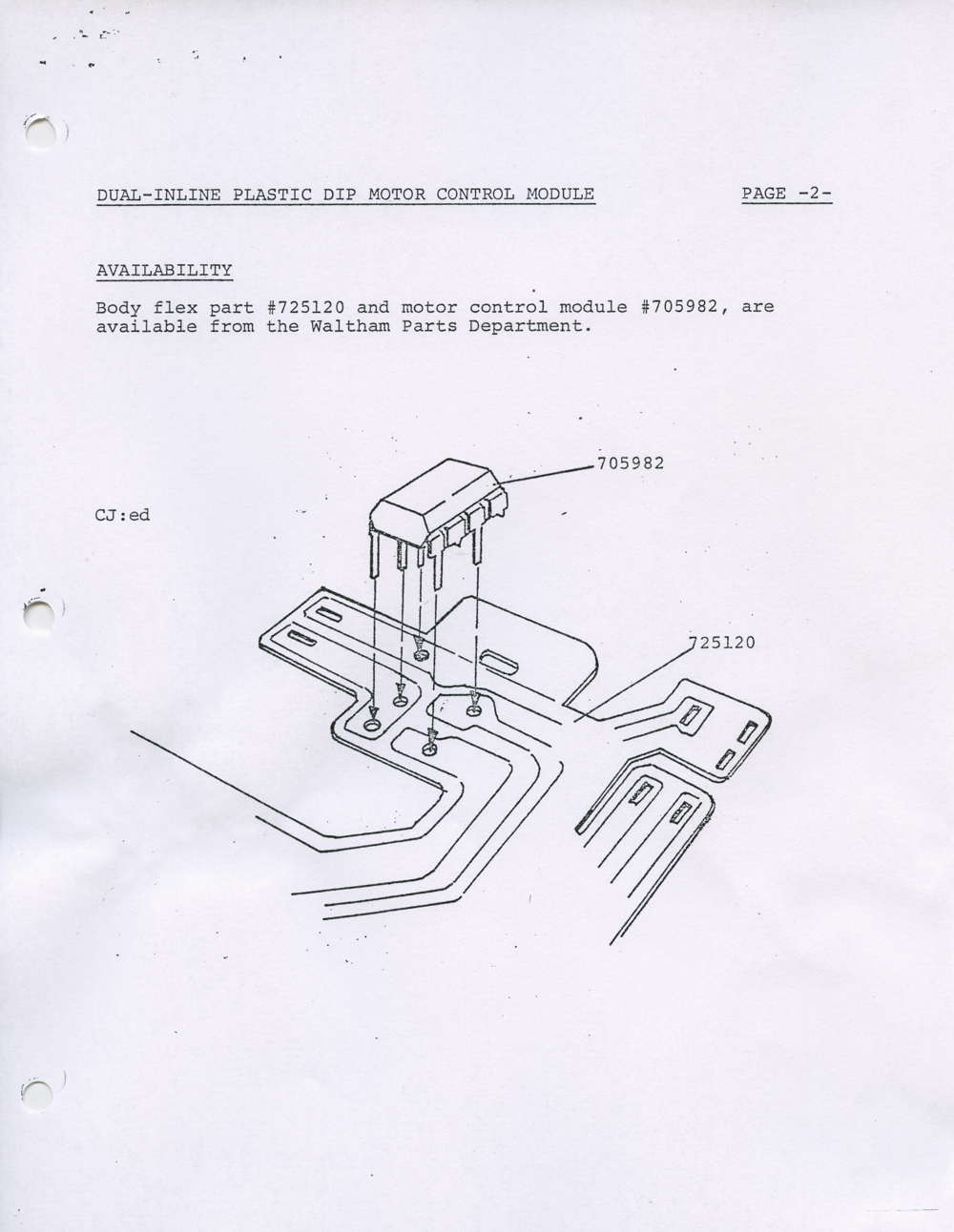
Here we can see the migration from the MCC (TO-5 motor control circuit) to the plastic DIP MCM (motor control module). We can also see the bodyflex.
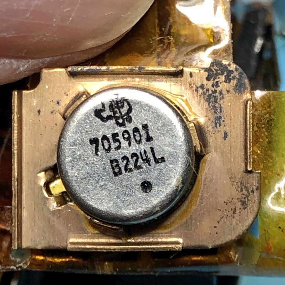
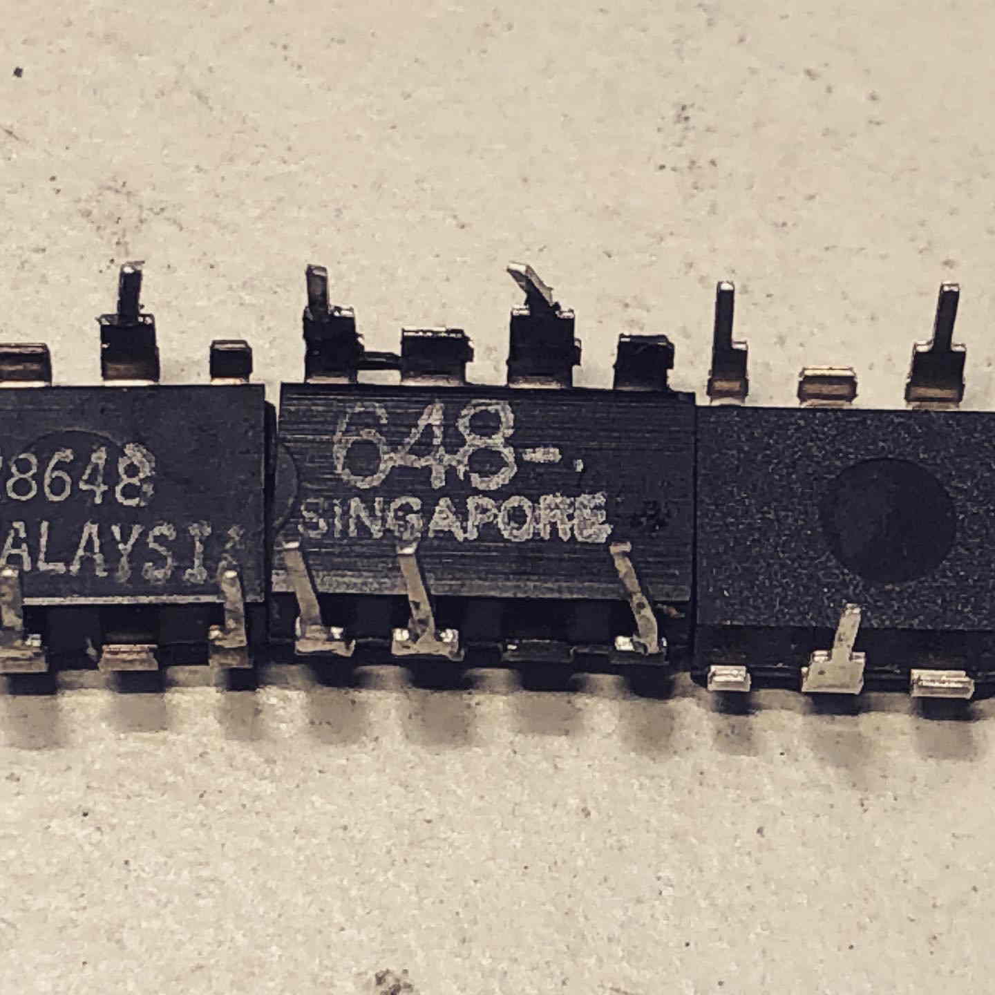
We now know that the part labeled in the bulletin as 705982 is a TI chip: SN28648P.
I have been looking for a feasible alternative, even contacted TI. Only to find a stash of old new stock chips:
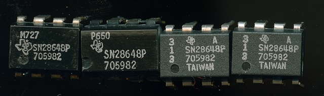
First two are original, they other is the new one. Checked it and works perfectly. This doesn’t mean that I have stopped looking for alternatives, on the contrary. That is why having our own PCBWAY manufactured gives us a simple way to make adaptations for new chips, in case necessary.
Caught my attention the fact that the chips came from the warehouse with 5 legs.
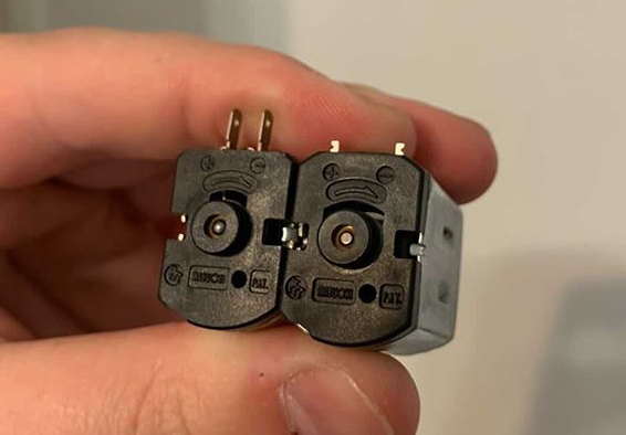
Here you can see, compatible motors with slightly different footprints.
There’s so many reasons to do your own flexpcbs, and with PCBWAY its so easy, as I say you always have a contact person (for me it used to be Julia, but now she’s on maternity leave, best wishes!), not only to replace the crappy capton ones, but to use new components, to make it look cool… And of course it can “help” with the use of external batteries, for i-Type film, maybe making bigger the target of the pogo-pins or many it’s something else…
So I can’t wait to have my flexpcbs, so, if you are intrigued as to how they turn out, and what is my experience and results, being an absolute newby, don’t miss my future post about the bodyflex flexpcb and PCBWAY.
Comments