A first look at the newer SONAR pcbs
So here I go again, with a totally new PCB design, just when I had something that looks solid and its working. So the question is WHY?????
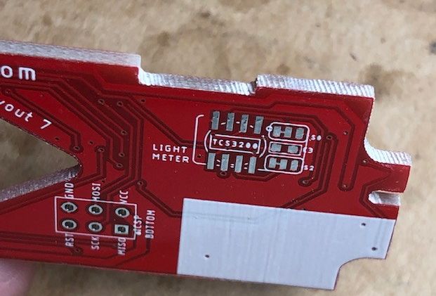
Well, let me explain it to you. When I ordered my last of PCBs I ordered three types of boards, all with the same basic design, one for 3-legged TSL235R one for the small SMD TSL237T and finally one for the TCS3200. The TSL235 that I used in the reworked ALPHA pcbs I have discarded, as the SM version is nowhere to be found. Unfortunately when ordering the PCB I made a mistake, the ones for the TCS3200 I made 1.6mm thick instead of the 0.6mm needed for the SX70.
Making such a silly mistake really made me mad. My first impulse was to reorder right away.
But then I thought: if I have to reorder, I might as well take the opportunity to try a new different design, of course also repeat the wrong PCB as well.
So let’s cut to the chase, I have always said that I wanted to a sort of “universal” PCB, one that could handle (properly) pre-alpha cameras, and then Sonar cameras. Easier said than done. This is my first try.
I will try to explain the basic problems that I have had to tackle concerning the new PCBs:
-
S4, concerning the solenoid-1 in pre-ALPHA (original and model2 cameras)
-
the sonar flexcable connection and sonar operation (I consider this a passthrough)
-
S1 “red button” switch to be compatible with sonar and, of course adding the “second” button for pre-focus on sonar
-extra pads for sonar cameras, and, as a consequence of that relocation of the flat cable connector.
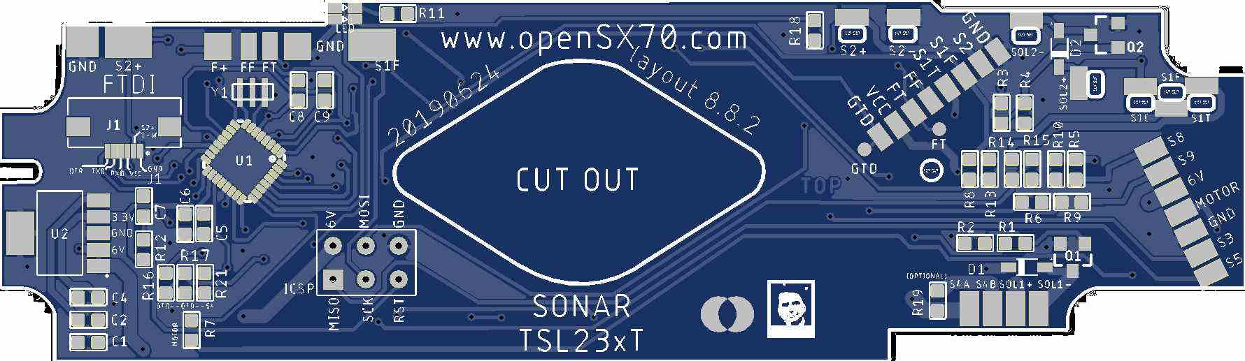
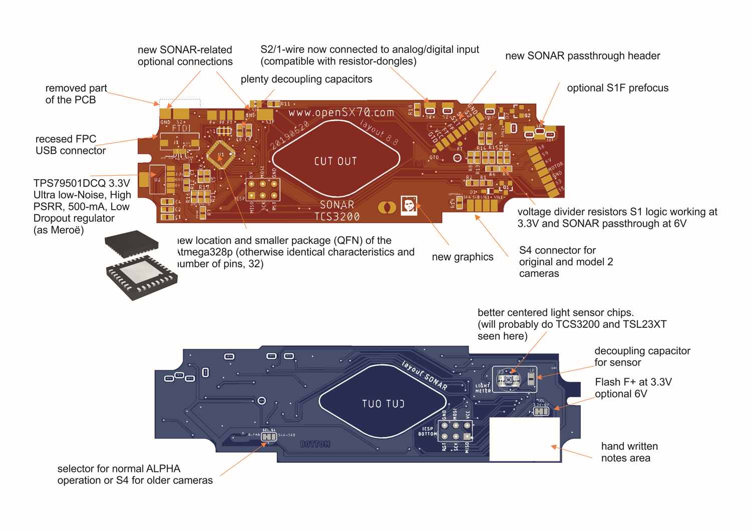
Off the bat the problem in SX70 PCB design is real state. If I have to add a new connector, and a few more components, I had to change the microcontroller package. That doesn’t mean I ditch the trusty “arduino-friendly” Atmega328P, but I needed the same thing in a much smaller box, so instead of the TQFP package I used I had to move to QFN, both 32 pins, otherwise both are exactly the same.
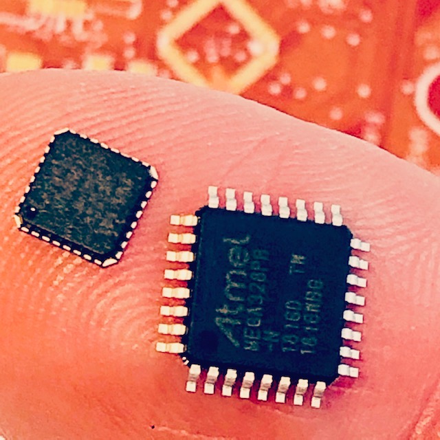
The problem with such a small footprint is, that is very difficult to solder, I am not even sure I will be able to do it, but, I guess due to my ignorance, I figured I could do it, maybe with hot air an patience.
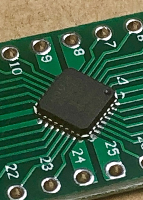
Fortunately I have a PCB adapter so I will practice with it.
For added “bonus points” I would like to program the chip with the bootloader (and with Blink2) before I solder it. That helps me later when I plug it in for the first time, if it starts to blink in red and blue, I know inmediately that at least something is working.
So why not? I ordered a socket in Ebay for seventy bucks. I mean, the thing doesn’t even have legs, I didn’t know that those adapters even existed.
So the plan is to relocate the Atmega to the other side, add a few points that exist in the original Sonar PCBs, much to my despair where I put my flat cable connector, and add the sonar-flex cable header.
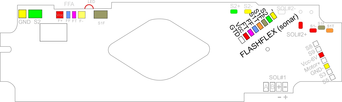
As for the sonar, if you see my picture color-coded, it basically a repeat of other nets that we already knew. Adding of course pre-focus button that (obviously) does not exist on non sonars.
The way I aproach the question (of the sonar itself) is that I really don’t know what to do with it or how to handle it. Without going into much detail here since I intend to do a follow-up of this post, I treat the sonar as a blackbox. Let me explain it’s like the TV and the VCR, the sonar assembly is basically and add-on without truly much actual integration. In this case, for me, it good.
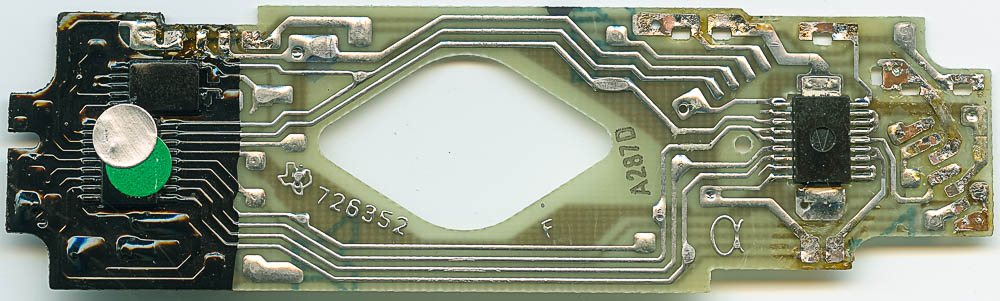
Looking at the evolution of PCBs, and granted that the original “ALPHA” PCBs were a major milestone (read “The Battle for the SX70”) both in the sense of cost, and manufacturability, but also, yield. Spoiler alert, Texas Instruments won the battle.
So in the evolution of PCBs we see, originally S4 next to the solenoid connection. I will also explain that in a different post, but I can only think that S4 was needed because of a limitation of the electronics. And it must have been expensive.
I am no expert on original SX70 PCBs but I think it has to do with the hybrid shutter (probably meant that it could do S4 and non-S4 solenoids?).
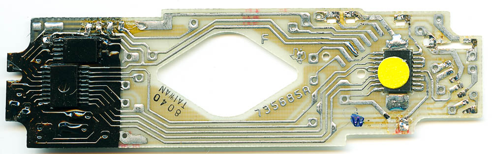
We see early alphas, there’s not much to it, but then, later on something appears where later the flashflex (connection to the sonar) will be. Also left of the F+ a pad shows.
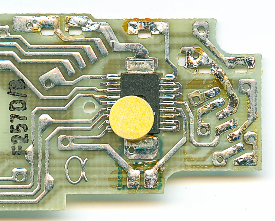
Here we can see a similar board. Still S1 (connection to the red button) is a simple on-off, connected to 6V (more on that in the future), and the flashflex header is incomplete: seems to have most of the same connections, and in the same positions it will have later. For instance, first on the right is GND, and then the S1, and the flash repeat connections. and then the two last (that are differentiated on the sonar seem to be merged) so instead of (from the left now) GTD and VCC both seem same. Weird. What is the purpose of that? If anybody know please contact me at opensx70 at opensx70 dot com please.
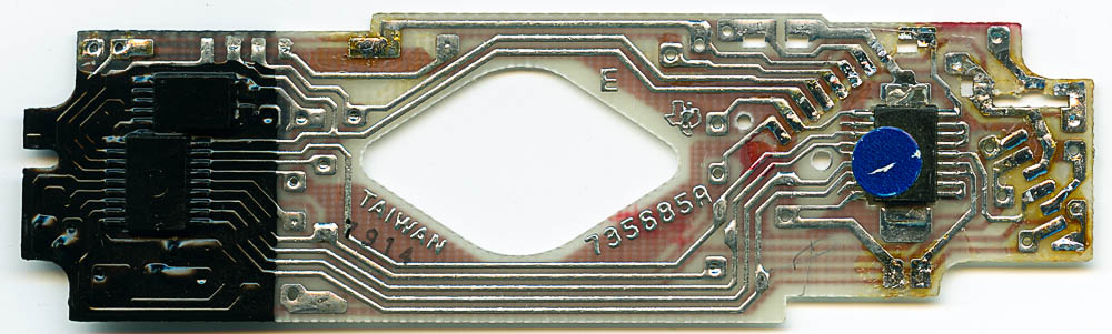
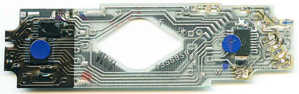
Finally we get to the sonar with is header going upward. Here we can see two red buttons, one for prefocus (called S1F) and another for picture-taking (S1T) and a common pin to 6V.
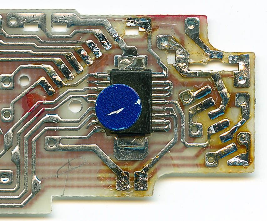
As you can see, I am not a smooth operator removing these boards, a broke and few tracks.
I don’t consider this a proper implementation of sonar and more a “passthrough” implementation. I figured I could make it at least work, as in an original camera. But who knows.
If you know the meaning of the blue, yellow, or some other colour dots, please let me know. I can only assume it has to do with calibration.
So finally here an explanation of my new PCBs. They are already on order. We will see if I can even solder the chip, let alone if the work, or something works!
In future posts I will explain the changes that I had to make in the red button implementation. The way (that I think) S4 works, and also my explanation of the flashflex and what I think the GTD signal means and what it does.
So to be clear, if all goes according to plan, this PCBs in theory at least, and by adding or removing components, and connecting jumpers, could be used for any SX70, up to sonar. BTW there are some sonars that have the viewfinder LED and some that don’t.
Does anyone know which models have it and which don’t? What is the difference amongst the different sonar versions?
By the way, this does not affect the timeline of the “product”, in the sense that the bottleneck now for a product would be the dongle, having a nice workable dongle is number one priority.
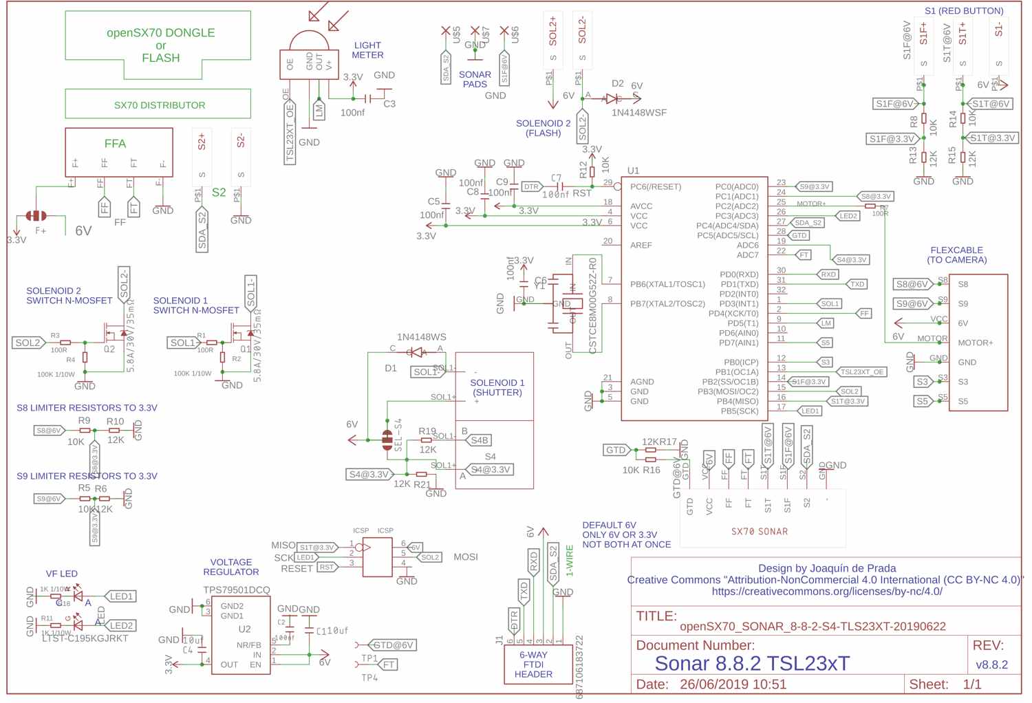
Finally here’s the schematic!
I really feel my ignorance makes me daring. But I promise I will try to learn from my mistakes. Anyway, if this works in any way, it will be the first ever “all manual” sonar SX70, with all the goodies that come with the openSX70 cameras. If it doesn’t work, I will try to come up with a good excuse!
Only time will tell. Oh, I see you have made it to the end of the post. Do me a favour please, post a comment, so I know someone read the post. Thank you.
Comments