OpenSX70 for Dummies (part 2)
Introduction
Disclaimer: Some people might think that I know electronics, well, the truth is that I actually don’t. I studied law in college. But I try hard. So everything I say from here on is probably “wrong” you have been warned.
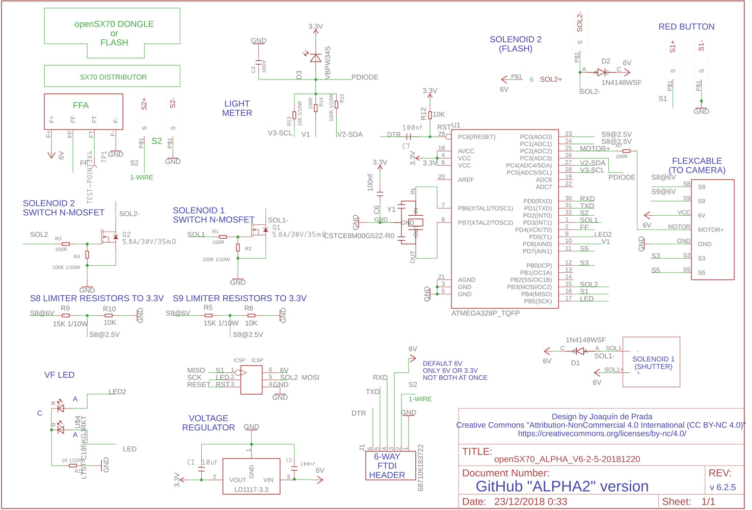
This is the full schematic of the alpha-2 board. I am goint to break it into parts (keep in mind that where you read 3.3V it is actually 2.5V):
This is the arduino. Just like any arduino. It is what I found to be a “bare minimum” arduino circuit. It needs a capacitor and a resistor for reset/dtr line, and an external crystal (actually a resonator: one 8mhz crystal and two capacitors)
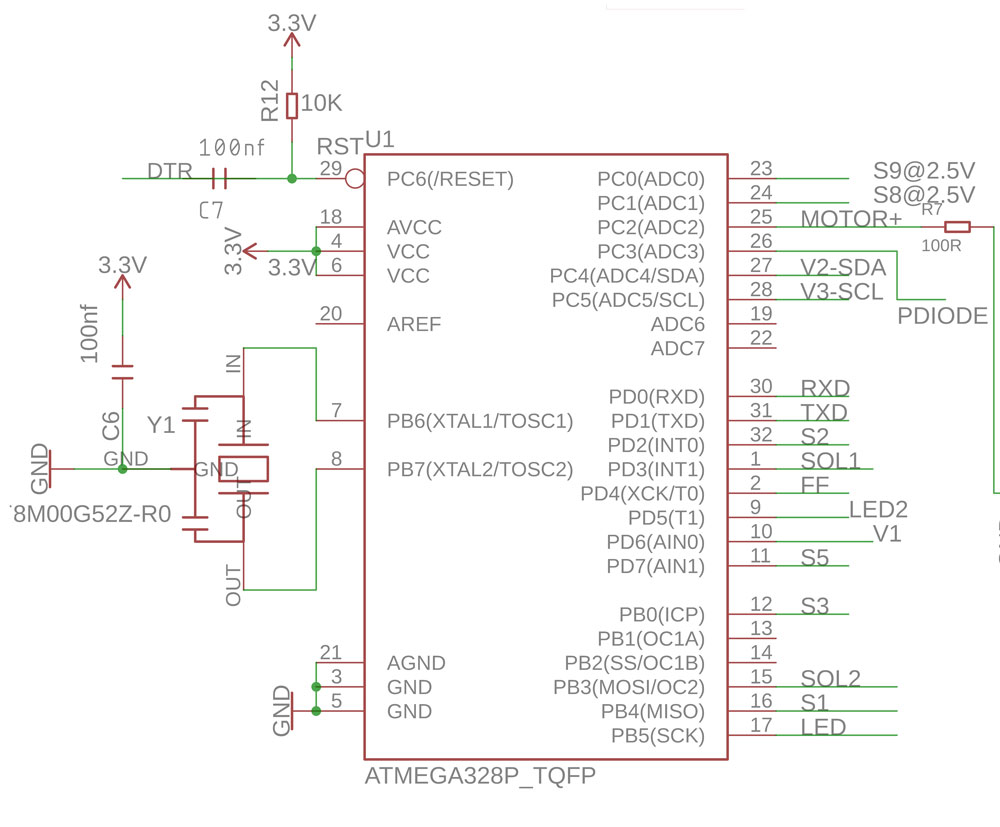
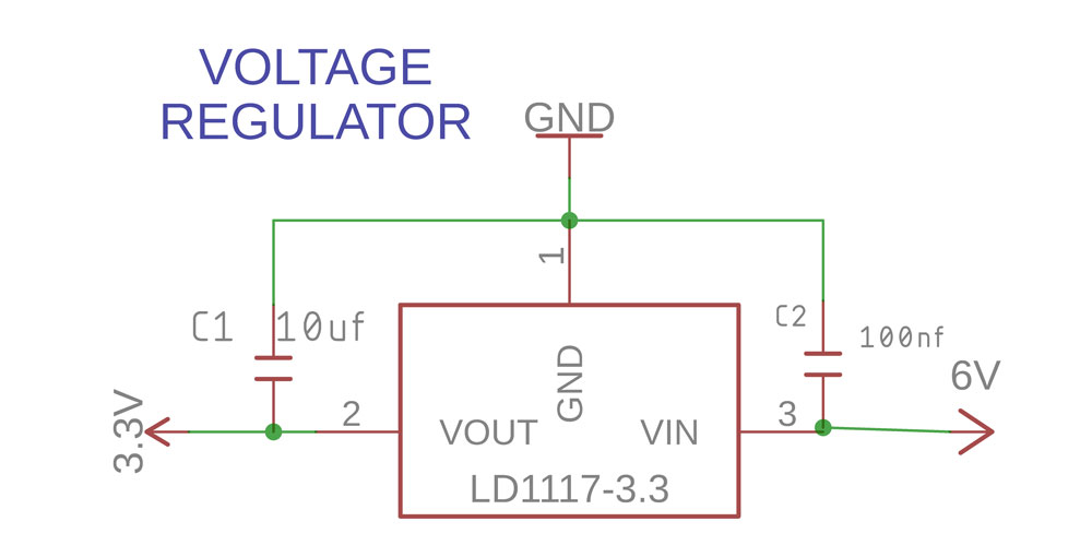
It is powered by 2.5V comming form and LD1117-25 regulator. This is the default circuit. In 6V out 2.5V. (Normally arduino is 3.3V, in our case we found more stable to run at 2.5V 8mhz)
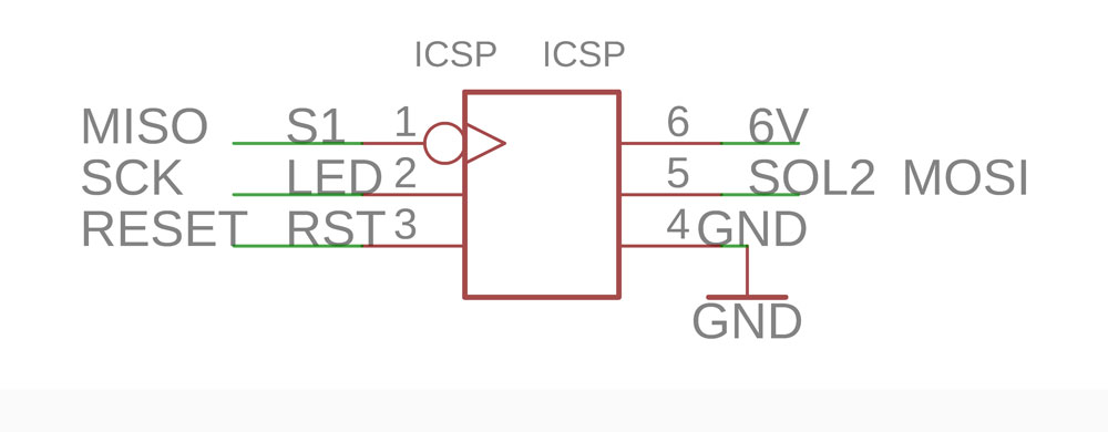
Then, as also “standard” Arduino blocks are the ICSP, the ICSP is a in-circuit way of programming the microcontroller, it is different from the (user-friendlier) FTDI in the sense that you can program the bootloader with the ICSP (which arguably makes the arduino an arduino). In my case I need that when I have the boards professionally manufactured and need to load the bootloader to the microcontroller.
Normally I programm the Atmega328P with an adapter and MiniPro programmmer, and once programmed with the bootloader, I put them in the PCB.
This of course I cannot do when the PCBs are manufactured in China, so I use a custom pin with six pogo-pins. You can see the jig in this blogpost.
And the FTDI is the “user friendly” way to upload programs (sketches in arduino lingo) via a simple USB cable and a computer.
There are a few things odd in our FTDI: First it is connected to an external board with small (and flimsy) flat cable (6way .5mm type “B”) But if you look closely I have use one of the 6 wires to connect my 1-wire communication.
This means that a control circuit (dongle) could be connected to the flat cable, without neet to use the flash socket. I am experimenting with such idea. The original idea comes from Marco of AnalogThings.. It is an amazing channel that I highly recommend. He even has a video on installing the openSX70 PCB. Thank you Marco!
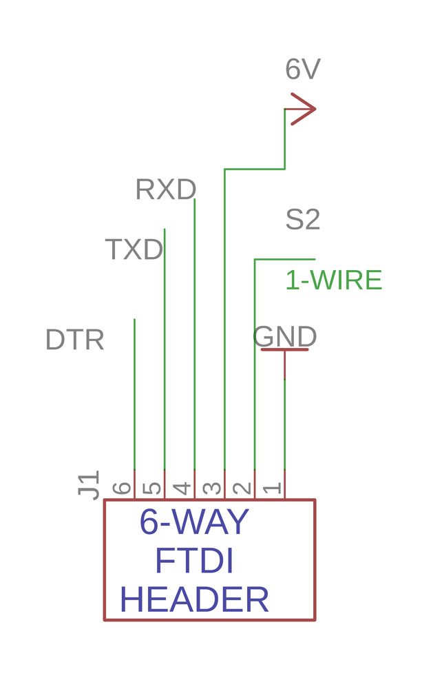
Both (ICSP and FTDI) are means of programming and communicating with the Arduino/microcontroller. The FTDI is the flat cable (6-way) connection, the actual FTDI 232RL is in a different small board.
Not only you can reprogram the arduino you can also use it to debug (serial monitor) that is, the camera or arduino printing on a terminal screen debug information about your program. You can reprogram the camera (USB) with the Arduino IDE or with the much simpler Xloader. This is like uploading a new firmware to a device.
The 7-way flexcable connector is the way the PCB connects to the rear of the camera.
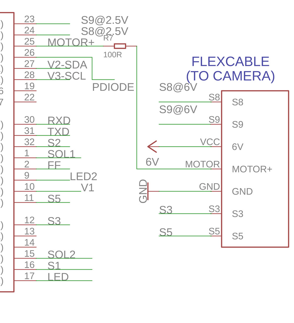
It has of course power VCC coming in at 6V, GND, and then one output to turn on the motor (MOTOR+). This is not connected directly, but I use a small resistor to protect the atmega. Then the motor has what is called the MCC, which is probably some sort of Mosfet.
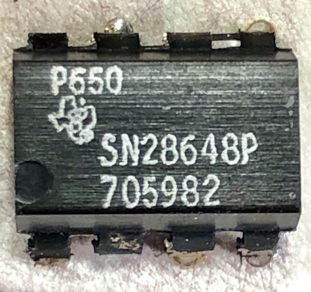 (this is the original chip next to the motor by TI)
Then switches S3 and S5 this are the switches that are in the gears. They are on or off depending on the possition of the gears. So we know where is the mirror. This is what I like to call mechanical electronics.
S5 controls the motor turning it on and off and S3 starts the so-called Y-delay. This delay is a small amount of time that the camera waits when the mirror jumps up to avoid vibrations. It is called Y (as in WHY?) because when designing the ASICs (the chips) both Fairchild and Texas Instruments engineers didn’t know much of the details of the camera operation, and kept asking the reason for the delay. You have to think that for the time, late sixties and early seventies, the level of electronic integration was unheard of. So the Polaroid engineers were very secretive about it… I recommend reading “The Battle for the SX-70” (electronics) by Tekla S. Perry, pusblished on the IEEE Spectrum Magazine in May 1989. Fascinating read.
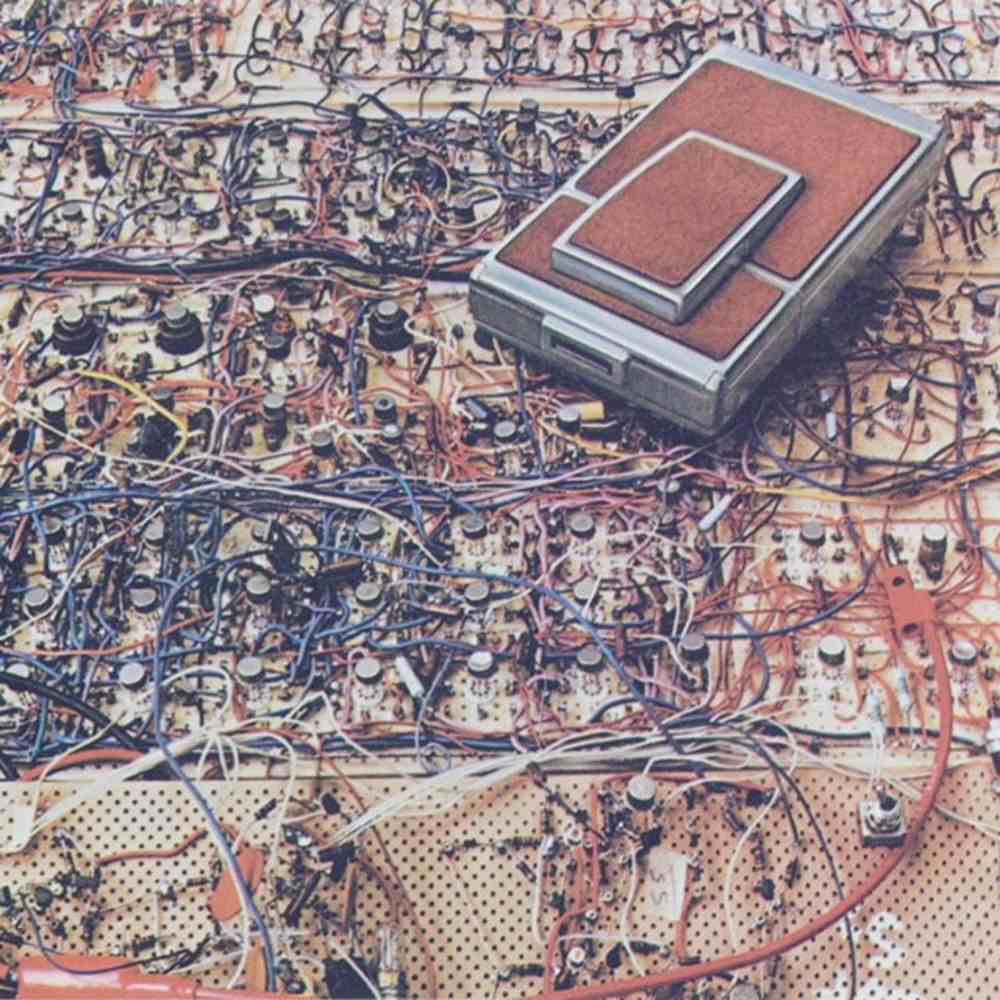
You can appreciate the level of integration from this picture of the original breadboard, equivalent to the actual circuit in the camera but with discrete components.
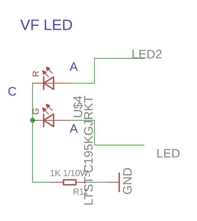
This is at least in part another starndard arduino bit, the LED, there is (normally) an LED built-in in port 13. I have another one so it is a two-colours LED. I think it is placed upside down. Ooops.
This switches (S3 and S5) are just like the switches on the wall, the close a circuit. In this case to ground (makes it easier for me) so I (the arduino actually) knows when to turn on the motor and such.
But wait, there’s more switches:
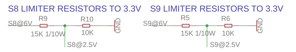
S8 and S9 are also switches on the camera. They tell the camera if the pack is just inserted and needs to eject the darkslide or if the pack (10 photos) is exhausted. There is a very specific logig accomplishing that. But the problem is, that when the circuit is closed (they basically “ON”) they connect to 6V. And that is a problem to for my arduino. Let me explain.
As I said before and have explained several times, there is a regulator (LD1117-25) that is a sort of voltage transformer. This turns the incomming (from the pack via the flexcable) 6V or 5.8V into 2.5V. I have explained somehow why is this needed.
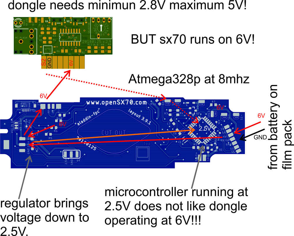
So I cannot connect this lines coming with 6V, I need to turn it into something more friendly to my microcontroller: yes! 2.5V.
This is a standard electronics bit, and you do it with two resistors: 10K and 15K. It is a voltage divider.
The final switch, is in fact an actual switch: the red button. This (contrary to the original camera) goes to ground when pressed. For the reasons stated just above is simpler to go to ground.
(when you have to different voltages in a circuit like we do, 6V and 2.5, positive or VCC is different, but negative or Ground or GND is the same for both voltages, making things simpler)
One note, in my schematic says “3.3V” but you should read always 2.5V.

So to explain (AGAIN!) what is a microcontroller/arduino is like a small computer that interfaced with the physical world.
This means that you can turn on things, lights, LED, or know (as explained before) when a switch is on or off, and DO SOMETHING accordingly. That is very cool. It can be an input or an output.
Thus far we have seen information coming from the camera, letting the “brain” know if the button is pressed, if the mirror is up, if the counter has run out. And act accordingly.
Now we need to “turn things on” and there are basically three things in the camera. The motor. We just say to the arduino “turn it on” and wham! the motor is on.
This is sample code to turn on the motor:
digitalWrite(Motor, HIGH);
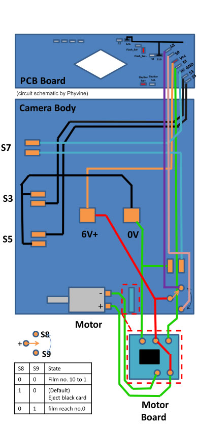
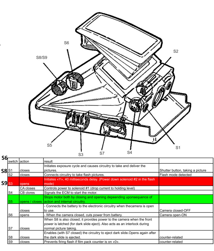
This picture will help you understand all the connections on the SX70 camera. The graphic by Phyvine.
Continuing with motor operation, this is so simple because there is already in the camera a mosfet (in the back close to the motor).
The mosfet is basically a switch. If you imagine an output on the arduino as faucet, sometimes we need much more water than it can deliver. So we use this.
You can see here three more “S” switches on the picture: S6, S7 and S4: S6 and S7 are easy, they are the way to turn on the camera (there is no ON/OFF switch). So S6 gives power to the camera when the camera is up or erect. But you also need S7 “ON” and that happens when the door or the latch with the rollers is closed. You need both engaged.
Then there’s S4. That is not so easy (correct me if I am wrong) this is phisically engaged with the Solenoid 1 (shutter operation) and acts like a sort or relay with two positions AC and BC. I think this was used in early cameras (pre-ALPHAS) to “know” when the solenoid was engaged all the way and so switch to LOW POWER mode. Maybe they used a simple resistor… It was vital for the engineers designing the camera to avoid noise and interference and save power. That is why they used all the juice they got to “move” the shutter into position, but once its there, there is no need to waste resources so they turned to LOW POWER.
But we also need to move two powerful magnets: the one that closes and opens the shutter blades, and the one for the flash, that limits the aperture. These are Solenoid 1 and Solenoid 2.
Here there is no mosfet in the camera, so I have to provide one for each:
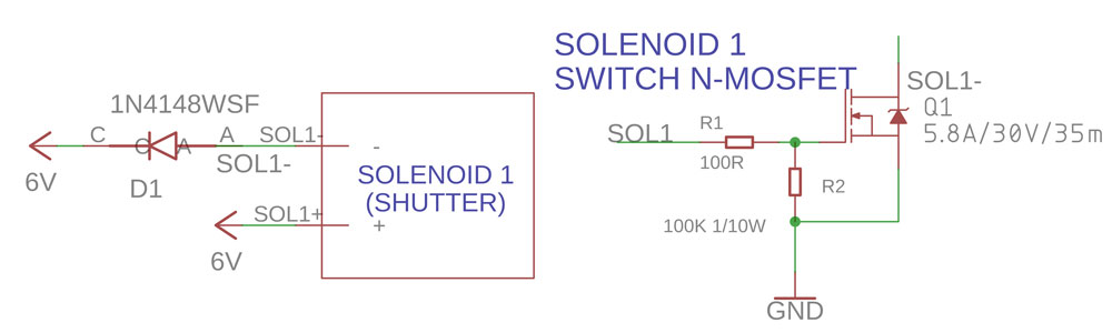
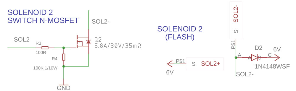
This, again, is as simple as it gets. Textbook electronics.
We are almost done, bear with me.
The flash socket (8-way) on the camera, is again another active circuit. The polaroid engineers had to devise a way to know if the bulbs on the flashbars where good and which one to fire. They didn’t want to waste people’s expesive shots or bulbs. So the FFA circuit detects which buld to flash, and if there are none, it doesn’t let you take the picture. Also it there are no pictures left in the pack (remember S8 and S9?) it doesn’t let you waste the flashbar bulb. Amazing.
Many people think: great! we have an 8-way physical interface with the camera. This makes everything simple doesn’t it? Well not that quick, it is not that simple. Remember we have all that circuitry I just mentioned above. So in practice we only have 3 wires to the socket. Only 3 out of 10!
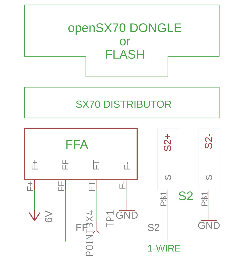
So there is F+ F- this only power the flash, VCC or 6V and Ground. Then there is FF. This signals the flash to actually flash. Then the ICs hidden under the socket select which of the five shots on the flash bar should fire. There is also a FF line, that I have no idea what it does. If you do please let me know! Also, please be very carefull when desoldering and solderind this wires.
So now what…? wait, there is more we have S2+ and S2-. This is a switch like S3 and S5, and only thing it does on a regular camera is to inform the brain that a flash is inserted. If you have a flash for the SX70 (any flash, a flashbar or electronic) you can see that of all the eight “pad” that there are, the two on the right are connected, shorted. This way the camera know that there is a flash. Great.
But here is where we take the oportunity. Since S2+ is the thrird “wire” to the socket, we use this as a means of communication with the dongle.
Yes! the chip on the dongle is the DS2408, from Dallas. This chip uses a system that apropriately is called 1-wire. One wire lets us convey critical information to and from the dongle. Turns out it a “port expander” in practice it lets me have 8 inputs or outputs.
So the dongle has (as of now) 6 inputs and 2 outs. So the Selector needs 4 inputs to let the microcontroller know the position (the shutter speed selection or whatever), then the actual switches S1 and S2 use a port each, and finally now as outputs we have the dongle LED and the flash optocoupler.
Various spur thoughts: we have eight but we could have any combination, say 2 LEDs and only one switch. Another though, a few people see no use for the second switch, a see it more as blotch on the user interface. Making the user inferface more confusing. Dunno, maybe. My final thought is… maybe using one of the “precious” DS2408 ports to trigger the flash is a waste. Maybe it can be done as “normal” flash. Maybe. By the way, we use another regulator to bring the power in the dongle (for the DS2408) to 2.8V, that is within the range that the chip operates.
My comment in the user interface. Maybe not a switch, but perhaps a pushbutton to set options.
My friend Santi from AnalogueWorks (more on that soon) has this idea of having one (or two, which eye do you use to focus? I use the left) backward facing to assist on getting the shutter speed: just imagine, you keep moving the speed wheel and when the “adecuate” speed is reach the light turns green. Of course you can disregard this and choose whatever speed you fancy. This is complementary of course of the viewfinder LED.
So we finally get to the light meter sensor. (Spoiler: it’s not nice!)
I initially started with the “fancy” BH1750 light meter chip. This a really small I2C chip that “tells” in lux, the light value.
IT WAS A DISASTER.
Let me explain you why, and there are many many reasons: it was too small to acommodate the camera window and the little light that makes once it has gone througb the darker/light dial and the so-called lollypop lens. Also it was so small it was almost impossible to hand solder. And of course was way too slow. The reading were imprecise because it is not thought out to be where I placed it. Conclusion: NOT NICE.
So I started to look for a new light sensor. The idea was to find something a close as possible to the original light sensor in the camera.
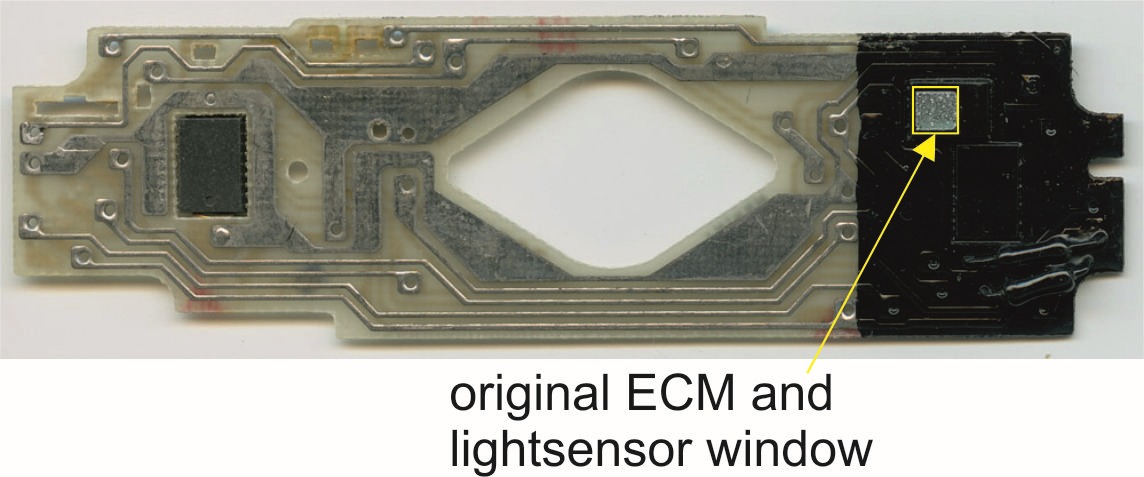
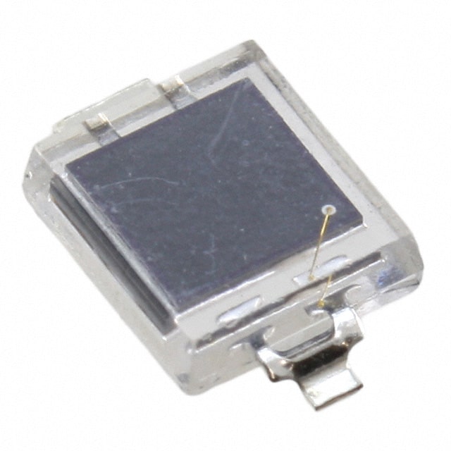
Making a long story short, the original light sensor was a photodiode, so after testing a few I selected the SFH2430 from Osram.
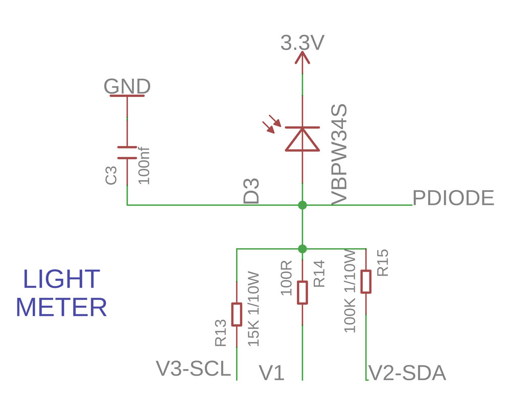
But here’s the thing, it is not that simple. You cannot just connect the photodiode to the arduino analog imput and meassure the light (By the way an analog input in the arduino gives you a value depending on the voltage on the pin on the arudino from 0 to 1023). You need to use a resistor to gauge the sensitivity of the photodiode, there is no one-size-fits-all… So whit the help of my friend Peter we thought of a “clever way” to connect different resistors to the arduino to select the sensitivity of the sensor. It works… sort of… but it is not really stable enough…
When you explain this to people “in the know” and say phrases like “clever solution” and things like that you basically f***ed up. Oh well, we will keep on trying.
This is the camera sequence from the camera repair manual it has on the information needed to program the software (I transcribed it from the original Repair Manual):
Comments