The ultimate guide to SX-70 600 conversions
Preface:
Hello everyone. My name is Jake, but you likely know me better as “The Instant Camera Guy”. At the time of writing this article, I’ve been tinkering with Polaroid cameras for over 12 years.
If you follow my live-stream repairs on my Facebook page, you might have seen a video I posted titled “the dark art of 600 mods” where I discussed the murky world of converting Polaroid SX-70 cameras to take 600 and i-Type film.
The current online consensus seems based around the following method:
“Replace the original capacitor on the PCB with a 150pf unit and the camera will then expose correctly for 600 film”.
This was the method I used for a few years before realizing that results often varied significantly. With a lot of experimentation and some research, I was able to formulate better methods and achieve far more consistent results. Given the lack of detailed information out there, I thought it might be nice to put a more in-depth guide together.
Why do such a thing? Well, community knowledge of the SX-70 continues to grow. As the years go by I find myself still constantly learning and constantly improving my skill-set. I learnt from my own research and from my own mistakes and now you can learn from me.
At the time of writing this article I’ve been performing 600 conversions for roughly 3 years. Initially I was hesitant to perform these modifications. This was partly out of laziness (since I did not possess a de-soldering gun at the time, and using braid is tedious!), but mainly because the purist at heart wanted to keep the cameras as original as possible.
However, as the retro revival of Polaroid cameras continued to grow, so did availability of film in physical stores. What I noticed is that 600 and i-Type film started become more and more readily available while SX-70 remained a niche item. This is perhaps not surprising when we factor in that 600 type cameras outsold SX-70s by a factor of 20 to 1. As such, client demand for 600 and i-Type mods soon became overwhelming. I spoke to a few others repairers who informed me that you could easily modify any SLR model SX-70 with a Texas Instruments shutter by replacing the original factory capacitor with one valued at 150pf.
Generally I found that this mod worked ‘okay’ for the most part. I found that indoor photos were usually really nicely exposed, however outdoor photos on bright days were sometimes a bit over-exposed. Truthfully, in my early days of modding I didn’t pay much attention to the nuance of film exposure and exposure levels.
This was because I cut my teeth on instant film during The Impossible Project days, where film batches were experimental, changed constantly, easy to over-expose and often seemed to require a constantly changing degree of compensation. In fact, even as I’m writing, Polaroid Originals has an article explaining what L/D wheel settings to use for various scenes to ensure the best possible exposure. Why such variance in settings for different cameras? Is this to compensate for new film? Or is it compensation for a camera that is 40 years old and likely needs a service?
Additionally, living in Australia meant that film was never as ‘fresh’ as the supply in Europe. Over the years I grew to assume that wishy-washy and unpredictable results were all part of the fun of instant film!
In my decade of shooting Impossible Project film, I got into the habit of disabling the auto-reset of the L/D wheel when I refurbished cameras. That way, the camera could be left on a certain setting without it returning to the middle after opening/closing the camera. This helped a lot with certain batches of film that required over or underexposure to get the best results.
So after arming myself with a fancy new de-soldering gun, I went about my merry way, slapping 150pf capacitors into the cameras of anyone who wanted them converted. In 3 years of doing conversions as described above, I never really had anyone complain. My assumption was that my modding-skills must have been good, since everyone was apparently happy. Right?
Probably wrong…
More recently, with life returning to ‘normal’ in a post-covid Australian summer, I started having cameras that I’d I refurbished for clients be returned to me because they were producing VERY overexposed photos, generally when outside in full sun. These were cameras that I had completely refurbished, ensuring their electric eyes were cleaned, a brand new 150pf cap installed and the PCB totally re-soldered. But despite this, they were still producing over-exposed photos even with the L/D wheel at full dark.
Eventually I decided enough was enough. The conversion process I was using was clearly too rough and I needed to do further research to expand what knowledge I already had.
I’ve spent the last few months experimenting, documenting and I want to share my findings with the world.
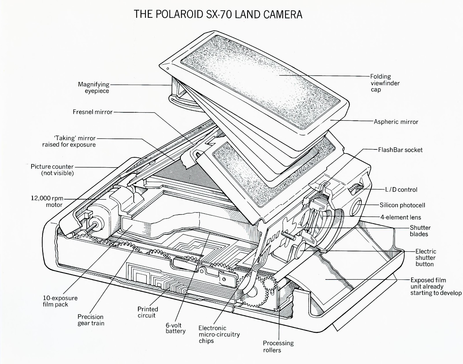
Chapter 1) How does an SX-70 shutter work?
If you want to understand how to convert a camera to 600 film it’s important to know how the shutter works. The shutter in an SX-70 is an incredibly unique design. In the official repair documentation, Polaroid stated the following:
The shutter employed in the SX-70 camera is unique. No direct comparisons should be drawn between the manner in which it functions and the function of other Polaroid electronic shutters. No manually adjustable or fixed aperture is employed. When a picture is taken, two shutter blades, with specially shaped cutouts, open the lens from a totally closed position to a suitable aperture. The two blades then reverse direction and again shut off the optical path. These same two blades also contain a similar (although differently shaped) pair of cutouts that open and close the light path to the photocell in like manner.
An SX-70 shutter consists of two sliding blades that travel in opposing directions through the middle of the rear lens cell. These blades feature two openings that allow light to pass through the lens and into the film chamber, as well as through the front housing window and onto a light sensitive photo-cell called the ‘electric eye’. The lens opening is a tear-drop shape while the electric eye opening has a stepped triangle-shape.
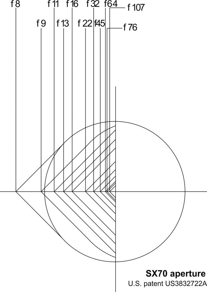
Unlike conventional cameras that have a separate aperture and shutter assembly, the aperture value and shutter speed in the SX-70 are COMBINED and continuously variable throughout any given exposure. Depending on how far the blades slide past each other, the opening for light to pass through may be very tiny (a small rectangular pinhole) or it may be very large (a circular opening with a maximum aperture of f8) or somewhere in between (a sort of diamond shape). Similarly, the opening for the electric eye varies too, depending on the distance of blade travel. It may form a tiny pinhole, a cross-shape or a rectangular slit.
The blades are able to move during an exposure through use of a solenoid. A solenoid is a type of electromagnet. This solenoid produces a plunging movement when electricity is passed through it. Simply provide power to the magnet and the plunger is pulled inwards into its housing. The solenoid plunger is spring loaded, so that when power to the magnet is cut, the plunger springs back into its original position. This plunger connects to a little arm which attaches to the blades and slides the blades past each other until. Power the magnet and the opening closes. Cut power and it opens up again.
There is an excellent promotional video from the early 1970’s on YouTube made by the Eames foundation that shows the exposure process in action. I highly suggest you watch it (or listen to my dance-remix version of it!).
Effectively the way the shutter cycle works as follows:
- The shutter’s default position is wide open. This is because the camera has an SLR viewfinder system, and the lens needs to be unobstructed for you to focus and compose
- When the shutter button is pressed, the first step is for the solenoid to engage, causing the blades/lens opening completely close
- The motor turns gears in the gear-train which cause the internal viewfinder Fresnel/mirror assembly to rise inside the camera. This will allow light coming through the lens to bounce off a mirror and down onto the film
- Once the mirror is up, the power to the solenoid is cut, allowing the blades to begin sliding into the open position once again
- As the blades slide open past each other, not only does light begin to pass through the lens opening and into the film chamber, but light also passes through the electric eye opening and onto the electric eye. The total amount of light (intensity and duration) reaching the eye is transformed by the eye into an electronic signal that regulates the length of time the film is exposed. This is known as the ‘integration cycle’
- The electric eye integration cycle works similarly to how your flushing toilet works. In a toilet, after you flush, water begins to fill the cistern, in preparation for the next flush. Once the water has filled the cistern up to a certain point, a valve is activated that stops the water so the cistern cannot overflow. Similarly, once the electric eye has received enough light, the logic circuits power the solenoid once again, causing the blades to cease any further travel and slam closed. So think about the electric eye like a bucket/cistern filling up with water. When this metaphorical bucket of light is full, the solenoid is powered on again.
- With the lens opening once again completely closed, the motor then engages once more and the gear-train comes to life again, ejecting the film and lowering the mirror inside the camera.
- Once the mirror assembly is re-set and the film completely ejected and the shutter button released, the solenoid power is cut once again and the shutter re-opens. The camera is now ready to take another photo.
The length of time that power is cut to the solenoid during the exposure/integration cycle is dictated by a capacitor/resistor (C/R) circuit. How exactly the C/R circuit works is a very complicated subject, so I will skip on the in-depth details here.
What you DO need to know though, is that should you remove a capacitor or resistor and replace it with one of a smaller value, the solenoid power will be cut for a shorter duration, effectively causing a shorter exposure time. A higher value replacement would have the opposite effect.
In a nutshell the effect of capacitors in this integration cycle circuit is:
Higher value capacitor = greater exposure value (ie shutter opens longer and more light is allowed in to film chamber)
Smaller value capacitor = smaller exposure value (ie shutter opens for less time and less light is allowed in to film chamber)
Chapter 2) General theory on conversion from SX-70 to 600 film.
600 modifications are all based around the same basic principal; that 600 film is a higher ISO than SX-70 film and thus requires a shorter exposure duration
Depending on the literature you read (some sources appear to round the values down), the exact value of film ISO varies. SX-70 film is generally considered to be 100-160ISO and 600 film is rated at around 600-640ISO. Additionally, Polaroid Originals currently states that there can be up to a 1/3rd of a stop variance in any exposure, dependent on external factors such as temperature during development.
Regardless of exact values, this equates to around a two-stop difference in terms of exposure between the two films. Thus, to use 600 film in an SX-70 camera, we must increase the effective shutter speed/aperture value by 2 stops.
Modification thus involves altering the electronics to produce a ‘faster’ exposure. In cameras with Texas Instruments PCBs this can be achieved by swapping a capacitor. In cameras with Fairchild PCBs this can be achieved by swapping a resistor.
BUT… it’s not that simple!
BEFORE we modify the electronics, we must ensure other aspects of the camera are working as optimally as possible.
SX-70 cameras are pushing 50 years old already. That means there is potentially 50 years worth of dust, corrosion, oxidization, disuse and wear and tear. As a result, my experience has consistently shown me that SX-70 cameras tend to over-expose as a general rule. In addition to the capacitor/resistor circuit, there are MANY other factors affecting exposure that must be optimized if exposure is to be accurate. In no particular order some of these factors include:
A) Electric eye corrosion. Texas Instruments PCB electric eyes are notoriously prone to corrosion over time. What exactly causes this corrosion I am not 100% sure, but it causes a white crystalline substance to accumulate on top of and underneath the little blue infrared glass filter on the photocell. I find that photocell corrosion can affect the eye accuracy by around 1 stop if severe. This build-up is easy to clean on the front but is much harder to clean on the rear. This is because to access the rear of the glass filter it must be removed from the eye. The glass is sealed in place into the silicon and is generally held in VERY tightly.
Occasionally, if the corrosion is bad enough, the filter glass may be pushed up and out the silicon entirely, making it easy to remove, clean and glue back in. However… if this hasn’t happened… you will need to cut or force the glass from the silicon. Cutting the glass free of the silicon is risky, time consuming and requires additional cost and materials if the filter must be replaced. Ultimately one must decide for themselves if this effort and risk is worth it. Fortunately, you can compensate for severe corrosion by further reducing the required capacitor value. It should be noted that fortunately, Fairchild PCBs use a different kind of electric eye that seems much less subject to this corrosion.
B) Oxidization of the anti-static layer on the shutter blades. This applies to early model cameras that have a matt-black ‘painted’ layer on the sides of the shutter blades that touch each other. Truly, I do not know what this painted layer really does. Polaroid technical documents refer to it as ‘antistatic layer’. It seems this layer was initially created to reduce the possibility of friction from static electricity as the blades travel along each other. Later cameras (Model 2 and onwards) tend not to use this painted layer at all, and Alpha and Sonar models use a white waxy dry-lube to reduce friction instead. If left intact, the anti-static layer on early shutters can oxidize and scrape off over time. This causes the paint to accumulate and get sticky which will cause the blades to drag. Sticky blades can significantly affect exposure. Depending on when in the shutter cycle the blades stick, this could cause over OR under exposure
C) Corrosion/oxidization of the metal lens cell where the shutter blades enter. On earlier cameras with metal lens cells, the metal on the rear cell can oxidize over time, creating a rough surface for the blades to travel along, adding friction to the blade movement. If severe, the lens may need to be replaced, or the helicoid removed from the base cell and sanded back lightly. If not severe, I find that ‘coloring in’ the blade entrance with a pencil works incredibly well. The pencil adds a layer of graphite in the pitted metal that smoothes it out and acts like a dry lubricant. I refer to this as the ‘poor man’s Teflon’.
D) Bent shutter blades. Fortunately this is rare, but in the past I have seen blades that had a kink in them for some reason. Perhaps they were bent during a previous repair or it arrived that way from the factory. Bent and kinked blades cannot slide nicely past each other and will move more slowly. Broken guide posts can also cause blades to stick against the sides of the lens cell. Broken guide posts must be replaced. A 1mm screw will do the trick.
E) Non specific electrical gremlins caused by oxidization, corrosion and ‘silicon lottery’. General aging of the PCB can cause untold amounts of electrical gremlins. For example, oxidization of solder can cause formation of salts that add resistance to traces. Dry joints, cracked solder and damaged traces can all mess with the exposure times or cause other weird behaviors. Like wine, storage conditions can seriously affect how the board ‘ages’. Sometimes shutters can misbehave even if they appear to be in perfect condition. If you suspect a bad IC, try re-flow all the solder to its legs as a hail-Mary.
F) The tint of electric eye window. Earlier SX-70s have a frosted glass, clear translucent window that is generally paired with a Fairchild PCBs. Later models have a darker tinted plastic and are generally paired with Texas Instruments PCBs. The frosted one lets in around 1 stop more light than the later tinted ones according to my measurements. Be aware of this difference if you are swapping front shutter housings
G) The L/D wheel mechanism. The L/D wheel works by sliding a graduated filter over the electric eye entrance. This allows more or less light to the eye, altering exposure. Early model 1 cameras feature a different design to later models. This type of mechanism has a small hole in the graduated filter that lets slightly more light in than later versions. Be aware of this difference when swapping parts.
H) Dust/grime/oxidization of solenoid. The plunger can slow down over time with dust or grime and cause slowdown or sticking. Flush it with electrical cleaner if you suspect it is gummy
I) The pneumatic adjustment screw on the solenoid. The shutter solenoid has a calibration screw that allows for fine-tuning of the speed that the shutter blades travel. This screw is especially important for accurate exposures of brightly lit outdoor scenes. Adjusting this screw is a very complex topic and will get its own chapter later. Before changing any capacitors or resistors it is VERY important to make sure this solenoid screw is in its factory position. In all my testing, I’ve found that factory position of the screw on an SX-70 model is 2 and a half turns inwards from the screw head sitting flush with the body of the solenoid. It generally takes around 3.5 inwards to totally bottom out the screw. By 3 turns or more the blades will slow significantly. If you bottom it out, you have gone too far.
There are also outside factors that can affect exposure too, particularly due to the modern ‘recipe’ of developing chemicals used in the new batches of film. These have nothing to do with camera conversions, but are important to be aware of should you accidentally accuse your camera of having a fault!
External factors affecting exposure include:
- Temperature. Developing the film somewhere too hot or too cold will produce washed out photos. Extreme heat will typically cause very orange/purple photos and extreme cold may inhibit developing altogether and produce blank shots (especially with black and white film)
- Shielding from light. Polaroid film must be shielded from light to develop properly. Fortunately, current opacification chemicals in the film are pretty decent these days. In the days of Impossible Project film any light during development at all would totally wash out an image! Although this is now significantly improved, exposure to harsh external light during development can still produce washed out images and ‘ombre’ style gradient to your photos.
So what does all this mean? Well, it means that although simple in theory, a proper 600 mod is not necessarily a simple job.
All of the above factors MUST be considered and/or rectified BEFORE conversion if the camera is going to stand a chance at functioning optimally. Even then, there is no guarantee the camera will work the same as when it came out of the factory floor.
Chapter 3) Texas Instruments PCBs.
Texas Instruments PCBs (TI PCBs) are the most commonly found circuit boards on SX-70 cameras, and are one of the best documented. TI made PCBs for Polaroid for more than a decade, and made several revisions. In general there are three general varieties of SX-70 PCB: one made to suit the Model 1, 2 and 3, one made for the Alpha series and one to suit Sonar cameras. Fortunately, the layout is very similar across variations.
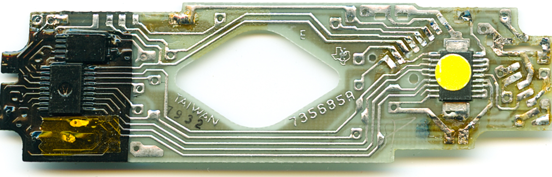
To convert a Texas Instruments PCB from SX-70 to 600 film, the capacitor in the integration cycle circuitry must be replaced with one of a smaller value. This capacitor is located next to a resistor below the electric eye and the silicon chip that sits below it. These parts are easy to find since they are the only through-hole components on the entire PCB. It should be noted that this area of the PCB is generally coated in an insulating substance. Early cameras use a clear-yellow substance, while later models use a black acrylic.

The insulation layer is easy to melt away with a soldering iron, or can be scraped off with a hobby knife. To remove the original capacitor, a solder braid or (preferably) a desoldering gun must be used to remove the factory solder, allowing the capacitor to be pushed free. Sometimes, if the insulation layer is thick, the capacitor must be carefully cut free from its insulation. After cleaning up the PCB traces with the soldering iron and some isopropyl alcohol, remove the 3 or 4 flash fire assembly legs and the PCB can then be carefully lifted upwards. The new, smaller value capacitor can now be inserted in place of the original. After trimming the legs of the new capacitor down, it can then be soldered in place. You must then cover the pads with some insulation tape to prevent short circuits against the metal chassis of the camera.
So what capacitor do you need?
The ISO difference between 600 and 150 is two stops, or a factor of 4. Thus, to ‘speed up’ the shutter, we must replace the capacitor with one at least ¼ of the value of the original. How do you know what value yours is? Well… the ONLY way to TRULY know the capacitance of the original capacitor is to remove it and measure it using an ESR reader.
Don’t have one? Fortunately, I’ve already done a stack of research for you.
Of the three types of TI PCB found in SX-70 cameras, many subtypes were made, using a variety of capacitor values in the circuitry. Fortunately however, Polaroid had the decency to generally only use one of several values in their boards. These capacitors are typically color-coded and are roughly valued as follows (note real values may be within +/- 10%):
- Early models with the clear-yellow insulation:
blue and red = 600pf - blue and yellow = 700pf
- blue and green = 800pf
- turquoise = 700 to 800pf
-
large black chunky rectangular capacitors = 700pf

Later models with black acrylic insulation are:
- small black capacitors = 800pf (found on later gen cameras, model 2)
- small black tube-shaped = 1000pf (typically alpha/sonar)
- teeny tiny small tooth-shaped capacitor = 1200pf (found on some Alpha and Sonar revisions)
I’ve measured many SX-70 PCBs and so far they were all one of the 5 values above; 600pf, 700pf, 800pf, 1000pf and 1200pf (+/- 10%)
So if we use the previously described theory of replacing the capacitor with one a quarter of the value, we get values of roughly 150pf, 180pf, 200pf , 250pf and 300pf respectively.

In THEORY this would mean that if your camera originally had an 800pf capacitor installed, a replacement of 200pf should allow the use of 600 film.
Many repairers tend to simplify the list of parts required and recommend using a single value of 150pf to convert ALL cameras. This certainly simplifies the parts list required if you are doing many cameras and will generally produce results that are “acceptable”.
In PRACTICE however it is not that simple. As described in the previous chapter, among other things, TI electric eyes are notorious for corrosion and ‘aging’. Put simply, some eyes seem to go blind more so than others. As a result, I’ve found that some cameras might require an 80pf capacitor to yield good results, even if the infrared filter is completely clean and free of corrosion. I’ve also witnessed the opposite, where a fairly crusty old electric eye in a beat up camera needed 150pf. After much experimentation, I’ve come up with this general rule of thumb
- First ensure the shutter is serviced by rectifying any issues outlined in the previous chapter
- Remove the original capacitor and measure its value with an ESR meter
- Check the quality of the electric eye and clean it as best as you can. Then, assess how clean the eye is. The value of the capacitor we use will change depending on how clean the glass filter is and is as follows:
a) For a perfectly clean electric eye, divide by a factor of 4
b) For a slightly hazy eye, try a factor of 5
c) For an eye that is completely opaque and cannot be cleaned try a factor of 6
When it comes to picking a replacement capacitor you may find it hard to source exact values so round down to the nearest value you can source.
For example, let’s say we have a black Model 2 with an 800pf stock capacitor. The eye in this one is perfect so we divide by 4. This gives us a value of 200pf.
We then take apart an SX-70 Sonar with a 1000pf stock capacitor. The electric eye is utterly crusty and can only be cleaned from the front. It is decided that replacing the eye, or cutting out the glass is too risky so in this case we will divide 1000 by 6. This gives us 166pf. 166pf capacitors do not exist, but 150pf and 180pf do! So in this case we round down and use 150pf.
When it comes to testing the conversion, one could rig up all kinds of fancy equipment to test the shutter, but I find that the simplest and most effective way to test the camera is to simply use some fresh film!
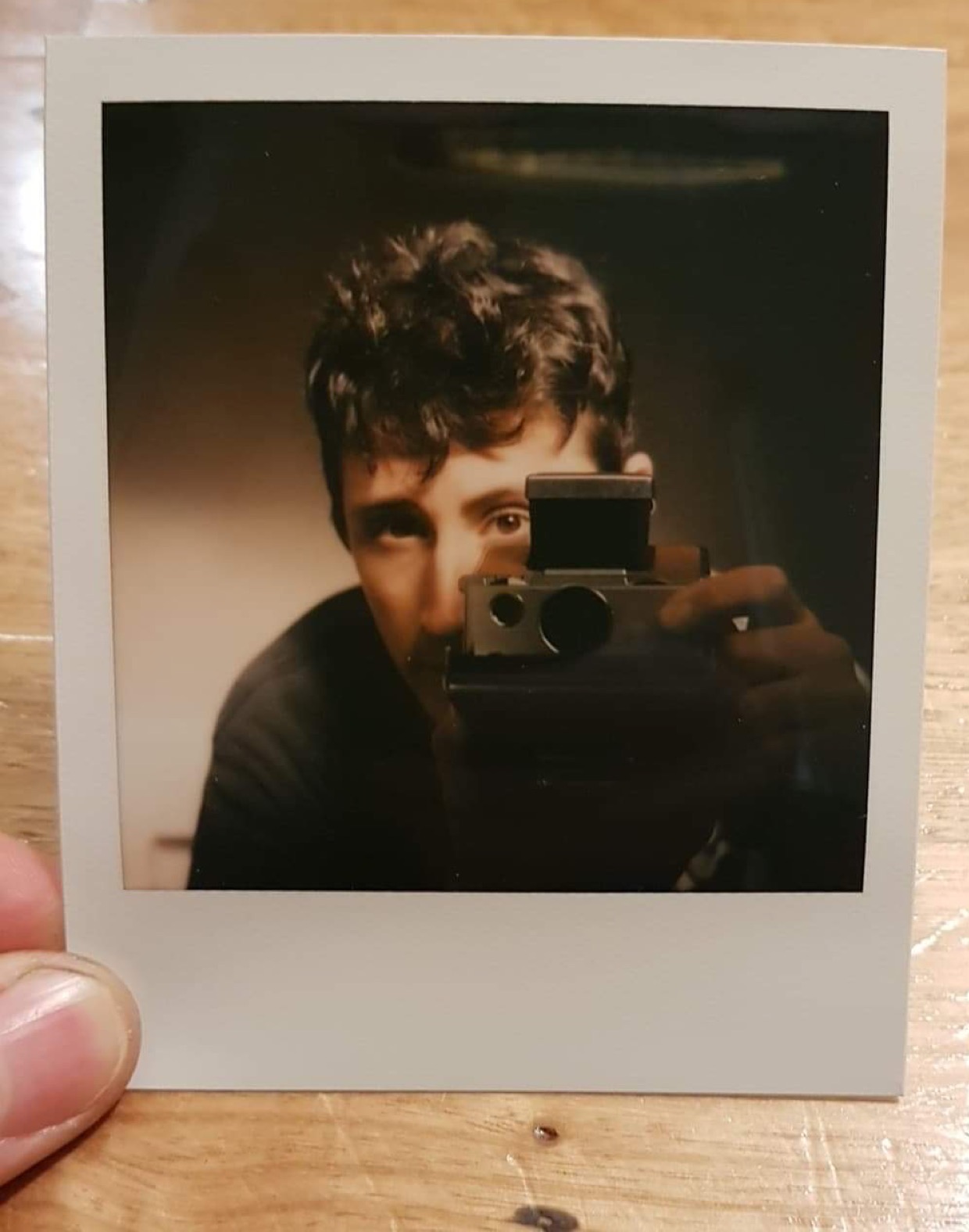
I recommend taking at least two test photos to make sure the camera works nicely. They should be taken with the L/D wheel centered. The first should be an outdoors photo, ideally focused at a subject at infinity in bright sun with a blue sky, EV17 or higher. The second should be indoors in a decently lit room, around EV9 or 10 at least. To test my own cameras I have found a successful method is to go outside and take one photo of my house. For the second photo I generally go inside and take a selfie in my bathroom mirror. My bathroom is relatively well lit and can easily expose a photo hand-held.
The indoor photo should be nicely exposed. It should not look too dark and dim. The outdoor photo should have a perfectly exposed subject, and the sky should be pale blue. If both are perfect, congratulations! Your camera conversion was a success!
Pictures not exposed properly? Well, the following is generally true:
- If BOTH indoor and outdoor photos are over-exposed, you will need to use a smaller capacitor value.
- If the indoor photo is perfect, but the outdoors photo is over-exposed, you can likely compensate by fine-tune the exposure using the solenoid screw, the process of which will be described in the final chapter.
- If the outdoor photo is perfect, but the indoor photo is very dim, you might need a larger capacitor value, and your solenoid screw may be set too loose. Again, explained in the next chapters.
Ultimately the only way to ensure your camera exposes things 100% correct is with some trial and error. Be prepared to buy a range of capacitors, and burn through a few packs of film before you are 100% satisfied.
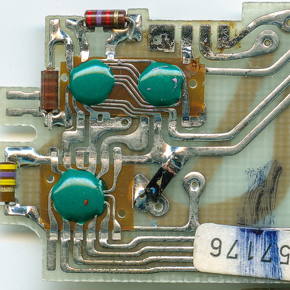
Chapter 4) Fairchild PCBs.
Fairchild PCBs are found in early generation SX-70 cameras. The history behind the competition between Fairchild and Texas Instruments is a fascinating one, and one that Joaquin has documented well on this blog. Effectively, both manufacturers were tasked with the job of manufacturing the ‘brains’ for the SX-70, at the cheapest possible price point. To do this, Fairchild opted to forgo the use of silicon chips in favor of acrylic-blobs-on-tape instead.

Instead of silicon, the ‘chips’ are made up of a piece of brown plastic tape, with the components placed on top, with layer of epoxy holding them all together. This was certainly cost effective, but collective community experience over time shows that this process made Fairchild PCBs far less reliable than their competitor. Simply put, the ‘blobs on tape’ are nowhere near as robust as a silicon chip, making them prone to damaged internal and external traces due to flexing and/or oxidization. I’ve refurbished countless original SX-70 model 1s over the years and I would estimate that 98% of the Texas Instruments PCBs work totally fine (if not with a corroded electric eye). With Fairchild shutters, I’d estimate that only 85% of them that I come across are still working properly.(COB, chip-on-board)

 LIFE magazine")
With that said, when they work, they tend to work VERY well, and they do have the advantage of being far less prone to electric eye corrosion.
Generally if you find a Fairchild shutter camera, the odds are high that it has NEVER been serviced. This is because when Polaroid SX-70 cameras were serviced by the factory, Fairchild shutters were generally thrown away and replaced by Texas Instruments models. If your camera has a Fairchild shutter, odds are it’s never been touched!
The technique for Fairchild PCB modification has only just been discovered! I must give credit to fellow electronics and Polaroid enthusiast Nick Cundari for this technique.
Arguably, this conversion is easier, because the component being replaced is surface mounted on the rear of the PCB, making it very easy to de-solder. There is no need to bend the PCB upwards to access the components.
Effectively, to convert a Fairchild PCB, the resistor above the electric eye must be removed, and in its place installed one with around 1/4 the value. MOST Fairchild boards have a stock resistor value of roughly 2700ohms. This generally means a replacement value of around 680ohms. HOWEVER I have seen some rarer variants of these PCBs that use a 10k ohm resistor!
The original axial-legged resistors that Polaroid used are very small, and I actually had a hard time finding one that fit. For this reason I recommend not using an axial lead resistor, and using a surface-mount resistor instead.
Nick’s testing of this modification on a 2700ohm camera using a 680 ohm resistor revealed a slight tendency to over-expose in bright sunlight. I have converted several of these cameras now using this method and personally have found a reliably consistent value replacement to be 550ohms. Like all aging electronics, mileage may vary and you may need to adjust values slightly +/-10%.
It would also theoretically possible to use a 1k ohm trim-pot or variable resistor to convert a Fairchild model to take 600 film. If you could find one small enough, it could be installed in the shutter housing underneath the electric eye, with small wires running up to the pads on the PCB. A hole could be drilled into the bottom of the shutter housing to allow a small screwdriver to ten adjust the pot. In theory this would result in an infinitely adjustable SX-70 exposure system that one could tweak on the fly!
The procedure for testing the Fairchild 600 conversion is the same as the TI PCB. Test both indoors and outdoors to ensure exposure is perfect throughout different lighting scenarios. In theory you may need to trial several resistor values. Fortunately, re-soldering and changing resistors on these models is very simple!
Chapter 5) Onestep SX-70s.
If you have read this far into the article, you should now have a good idea of what it takes to convert an SLR model SX-70 to take 600 type film.
So what is left to do? Well, what about box-type SX-70 cameras? Why would you even want to do this? Aren’t these cameras terrible? What with their cutsie-ootsie rainbow design and shonky single element plastic lens and all?
Well, you would be surprised! Although they are simple little beasts, I’d happily describe the Onestep series of cameras as ‘surprisingly capable’. Especially with some speedier film!
The conversion process for a Onestep is relatively straight forwards and is similar to the Texas Instruments conversion in that we will replace a capacitor to do it. The vast majority of models have an original capacitor has a value of around 200-250pf. Some early models though use 400pf though! So be sure to measure it!
Since we want to speed it up by a factor of 4, the new capacitor value I recommend is 50pf (or 100pf in a 400pf camera).
Unlike the SLR cameras, it is actually MUCH easier to fine tune the exposure once the new capacitor is installed. This is because Onestep SX-70s already have a factory calibration method built into the electric eye. In front of the photo-cell, behind the light/dark knob sits two graduated filters. One filter is attached to the L/D wheel itself and this filter is what moves when you turn the L/D adjustment knob. The second graduated filter is for factory calibration and sits just behind the first filter. This filter is toothed on one side (allowing for you to grip it and slide it up or down). Sliding the toothed side downwards lets less light into the eye. Sliding it upwards lets in more light. This second filter leaves lots of room for adjustment and fine-tuning should the new capacitor fail to yield perfect results first-time around.
The first step is to open up the camera. This involves opening up the film door, using a flat screwdriver, guitar pick or pry-tool to pop off the front lens housing, then sliding your fingers through the film opening, getting a good grip and pulling out the internal chassis/guts free from the body. Pronto cameras with variable focus lens elements are trickier to take apart, and the front lens element must be removed first.
Behind the electric eye you should easily be able to identify a capacitor and resistor sitting there in the ribbon cable circuitry. The capacitor is most likely going to be a green/yellow color, while the resistor will be brown.
If you are lazy, you can simply snip the legs of the capacitor and solder the replacement directly to the old legs. If you are a REAL technician however and want to do things properly, I’d suggest removing the little plastic cover for the rear of the electric eye, pulling the ribbon cable out of the way of the plastic chassis, de-soldering the capacitor properly and installing the new one directly to the ribbon cables.
After that, simply re-assemble the camera and test it with some film! Should it over or under-expose, simply adjust the factory calibration filter behind the L/D wheel. I recommend testing it in bright sunlight. If it works perfect in bright light, it should then work in dimmer light too.
Remember that this 600 modification will NOT affect flash units such as the matching Polaroid Q-light. All SX-70 cameras disable the electric eye when a flash is used, firing the shutter at a fixed speed instead. If you use a flash designed for SX-70 film with 600 film in the camera your pictures will come out over-exposed. Thus, you must use a flash designed for 600 film. Should you want a natively 600 compatible flash, I suggest the Mint flashbar.
Alternatively, the Q-light can be modified by using some 2-stop ND filter material or ‘flash gel’ over the flash lens. I recently took apart and modified a Q-light flash-tube lens internally using this technique and it worked perfectly.
Chapter 6) Solenoid pneumatics
Pneumatic adjustment of the solenoid was briefly mentioned in part 2 of this guide. Joaquin also has written a nice article going in-depth into the patent information of the pneumatic adjustment.
However, much of what Joaquin wrote about was specific only to the OpenSX-70 project, and is not so relevant to a standard SX-70 (whether converted to 600 or not). Because of this, I actually mis-understood the solenoid pneumatics at first, and spent a very long time telling people the wrong information!
Oh well… live and learn I guess! Time to make things right!
The screw on the side of the solenoid controls the amount of air allowed vent from the solenoid during its plunge. Much like a syringe, if you block the end, it becomes much harder to pull. Decreasing the amount of air allowed to vent makes the solenoid plunge a much slower process. Conversely, allowing air to vent freely will speed up the solenoid’s movement.
Polaroid engineered the solenoid like this to allow for fine-tuning of shutter speeds. After all, we are dealing with ANALOGUE electronics here. By the very nature of analogue technology, slight variance in components will result in a tiny drift in timings, even between two otherwise identical PCBs. Being able to adjust the shutter speed without drastically changing the electronics is advantageous.
So how does adjusting it alter the shutter? And what does this mean for exposure? Well… the answers may surprise you!
Turning the adjustment screw inwards (clockwise) will SLOW DOWN the solenoid piston. Unscrewing it (or removing the screw entirely!) will SPEED UP the piston.
In other words, the further in to the body of the solenoid the screw is set, the slower the shutter blades will move. The looser the screw is set, the faster the blades will move. The factory location for basically every SX-70 I have ever serviced has generally been the same. On average, starting with the screw completely flush with the body of the solenoid, factory position is generally around 2.5 clockwise turns. After 3.5 to 4 turns, the screw ‘bottoms out’ and cannot be turned any more. Official repair guides ominously warn you NEVER to bottom out the screw… but neglect to actually mention why.
So, what does all this mean? Is tweaking the solenoid a potential solution for fixing a camera that over-exposes? Or a solution for blades that are a bit sticky? Well… this is where things get complicated… very quickly…
Conventional wisdom suggests to us that if the camera is over-exposing, loosening the blades should help, since they will travel faster! Faster is great right?
Faster blades = faster shutter speed = decreased exposure = should help with over-exposure…
Right?
WRONG!
While the blades may physically move faster, you will likely find that loosening the solenoid screw will actually CAUSE OVER-EXPOSURE in bright daylight scenes!
So what the hell is going on here?
You will likely need to read and re-read this section many times to fully comprehend this. It is a very complex subject and I will try my best to simplify things. You will need a good understanding of the exposure triangle to comprehend the following, and will need to familiarize yourself with the design of the SX-70 shutter blades.
Remember that the SX-70 does not have a standard leaf shutter. The aperture assembly and shutter blades are one and the same. They are a combined unit. As such they have no true separate value for ‘aperture’ or ‘shutter speed’. This is because the design of the shutter means that aperture and speed are continuously variable. Instead of aperture and shutter speed, the only way to really quantify the exposure is to use “EV” instead. Exposure Value or “EV” is a way to combine shutter speed and aperture to a single value. EV was a commonly used system in the earlier days of photography but has become fairly uncommon to use in today’s world of digital cameras.
EV values can be converted into ‘equivalent’ shutter speeds and apertures to make it easier for people to understand, but converting EV values to equivalent speeds cannot ever give us a true answer of what setting was actually used..
For example, let’s assume we are using 100 ISO film in an SX-70.
An EV of 13 would correspond to:
- f8 at 1/125th
- f11 at 1/60th
- f16 at 1/30th
- f22 at 1/15th
What is the true answer? It is simultaneously ALL and NONE of the above.
When you see certain people brag that their modified SX-70 can do 1/2000th at f8… well… this isn’t really true. Aperture and shutter speed on the SX-70 are forever entangled. Two lovers destined to be together forever. Thus changing the effective ‘speed’ of an SX-70 must then affect the aperture in an equal way!
To understand the true effect of the solenoid plunger on the shutter blades, I find it easier to break SX-70 shutter exposure into three factors
- The amount of TIME the solenoid power is cut for during an exposure
- The DISTANCE that the blades can travel in this time
- The SPEED at which the blades are allowed to travel
The maximum DISTANCE that the blades can possibly travel is the point at which the lens opening is open at its widest. We will call this the “f8 distance”. f8 is the widest possible opening for the SX-70 lens.
Remember that the aperture opening in the shutter blades is tear-drop shaped. This means that if the blade does NOT travel the full DISTANCE past each other, the aperture opening will be smaller than f8.
So let’s consider three hypothetical exposure scenarios. All of these exposures will be taken with the solenoid set to factory position.
For our first exposure, consider a bright outdoor scene. In this exposure, the solenoid power is cut for a VERY short length of time, fractions of a second. During this hypothetical time the spring in the solenoid was able to move the blades A QUARTER of the possible maximum distance across the shutter assembly. This might correspond in a maximum aperture equivalent to f22 or so. Exposure is good.
For the second exposure, we will pretend some clouds have now rolled in overhead. As a result, the solenoid power is cut for a slightly longer length of time than in the scenario above. Since the plunger is can now travel for a few fractions of a second longer, the blades can travel a little further, and they now travel HALF the maximum distance. This might correspond to a maximum aperture of f11. Exposure is good.
For the third exposure we go indoors. It’s very dim, only lit by a small table lamp. As a result, power is cut to the solenoid for 5 entire seconds. The spring loaded solenoid plunger now has plenty of time to move thus and the blades are able to travel easily to their maximum possible distance and will stay there for the majority of the exposure. As a result, throughout the majority of this 5 second exposure, the effective aperture has been wide open at f8. Exposure is good.
Do you see how this works?
Now let’s re-visit the above three scenarios. The lighting conditions will be identical, but this time, we will adjust the solenoid screw to give less pneumatic resistance. We will loosen the screw 2 and a half turns. This means the solenoid can now plunge faster and the shutter blades will now travel more quickly.
In the first exposure, the solenoid power is cut for a very short length of time. However, since the blades are now moving faster, they are able to move further in the same length of time, and now move HALF WAY across the maximum possible distance. This might correspond to a maximum aperture of f11 instead of the original f22. The image is now very over-exposed.
In the second exposure, the solenoid power is cut for slightly longer. Again, the blades are able to move more quickly and thus travel further in this length of time. As a result of moving so fast, the blades now reach the maximum possible ‘f8 distance’ instead of the f11 of before. This corresponds to an aperture of f8. The image is slightly over-exposed.
In the third exposure, the solenoid power is again cut for 5 whole seconds. The blades arrive at the maximum aperture of f8 very quickly. However, since the majority of the exposure occurs over 5 entire seconds, the exposure is negligibly affected. The image is exposed more or less the same as it is on the stock settings. You realistically cannot tell the difference.
What happens in the above scenario is that due to the tear-drop shape of the aperture opening, enabling the shutter blades to travel faster means they actually reach a WIDER aperture SOONER in any given powering of the solenoid.
For dimly lit scenes, this has a negligible effect on exposure. However, in bright daylight scenes, the difference between reaching an effective aperture of f22 or f11 can mean the difference between crisp blue skies, and a washed-out mess.
“BUT HANG ON A MINUTE! That doesn’t make any sense!” you scream out loud!
The electric eye photocell meters the scene DURING the exposure! So why would speeding up the blades or slowing them down matter at all? If the blades travel faster, the lens and electric eye aperture opens faster too!
In theory this is correct. An increase in blade speed SHOULD simply mean that the same net amount of light reaches the eye but just at a wider aperture. In theory, EV should be identical. But in practice, this is not the case. In THEORY, loosening off the pneumatic valve should simply just make the camera use wider apertures and faster speeds for the same given exposures. In THEORY this could be used to allow the camera to produce more ‘bokeh’. But in practice this simply isn’t the case. At least not for a stock PCB.
Don’t believe me? All you need to do is take some photos on a sunny day with the pneumatic valve at different positions and you’ll see this very clearly.
So why, if both electric eye and lens opening are sped up at the same rate does over-exposure happen? Truthfully, I do not 100% know the answer, but it likely comes down to a limitation of 1970’s electronics and the fixed tension of the spring on the SX-70 solenoid.
Electronically there appears to be a very tiny ‘delay’ (fractions of a second) between the electric eye receiving the light information and the solenoid powering up again to close the shutter. With the pneumatics resistance set loose, the blades seemingly travel so fast during this delay that they travel far beyond the point that is necessary make a correct exposure, resulting in an aperture that is too wide and an over-exposed image.
Careful analysis of the electric eye opening in the blades reveals that the widest point of the eye opening actually occurs BEFORE the lens reaches its widest aperture of f8. This suggests to me that the design of the eye opening is compensating for some kind of delay.
Complicating matters further is the fact that the blades tend to open at a slower rate than they close. This is because the electromagnet in the plunger is much stronger and faster than the spring on the plunger. When powered, the electromagnet slams the plunger in very quickly. The spring takes a longer time. Altering the pneumatics seems to alter the opening speed more so than the closing speed.
As a result of the above, and likely many other reasons that I simply do not understand yet, the SX-70 shutter exposes on a ‘curve’, with brightly light scenes being more affected by altered pneumatics than dimly light scenes.
Ultimately, the theory is only part of the equation. In practice, what you need to know boils down to the following:
In brightly lit scenes on a standard SX-70:
- Loosening the solenoid adjustment screw will result in more light entering the film chamber
- Tightening the screw lets in less light
For the purposes of this guide, solenoid adjustment should be used to fine-tune exposure in BRIGHTLY LIT SCENES ONLY (EV15 at least or higher). Before testing film-testing a freshly 600-modified camera, you should first ensure the solenoid screw is set to the rough-factory-default position of 2 and a half clockwise turns from flush.
It only takes a quarter or 1/8th of a turn to quite drastically alter the exposure of a brightly lit scene.
For example, let’s assume you have converted your camera and find the following:
- indoor photos are perfect, but bright sunny photos are over-exposed, you might want to tighten the screw slightly.
- indoor photos are fine, but outdoor photos tend to be slightly under-exposed. You might want to loosen the screw slightly.
When both bright and dim scenes are perfectly exposed, you can consider your camera 100% working.
Given the many variables at play here, it may take a bit of trial and error to find the perfect capacitor/resistor/solenoid adjustment screw combination for perfect results.
Bonus:
What happens when you bottom-out the screw? As mentioned before, the repair guide ominously warns you NEVER to do this. So what happens? Does the camera explode? Sadly, it is nothing that dramatic. Bottoming out the screw results in the blades moving so slowly that they barely move at all during an exposure, resulting in a slow shutter speed and pin-hole sized aperture. Anything beyond 3 clockwise turns from flush and the camera will start to under-expose significantly because the blades cannot travel fast enough to reach wider aperture values.
Comments